Anchor for device package

a technology for attaching devices and packages, which is applied in the field of microelectromechanical systems, can solve the problems of difficult to attach other components, such as moisture and gas getters, to the package, and other types of components have not yet been commercially viabl

Inactive Publication Date: 2006-01-31
TEXAS INSTR INC
View PDF7 Cites 50 Cited by
  • Summary
  • Abstract
  • Description
  • Claims
  • Application Information

AI Technical Summary

Problems solved by technology

While some micromechanical devices, such as pressure sensors, flow sensors, and micromirrors have found commercial success, other types have not yet been commercially

Method used


Image

  • Anchor for device package
  • Anchor for device package
  • Anchor for device package

Examples


Embodiment Construction

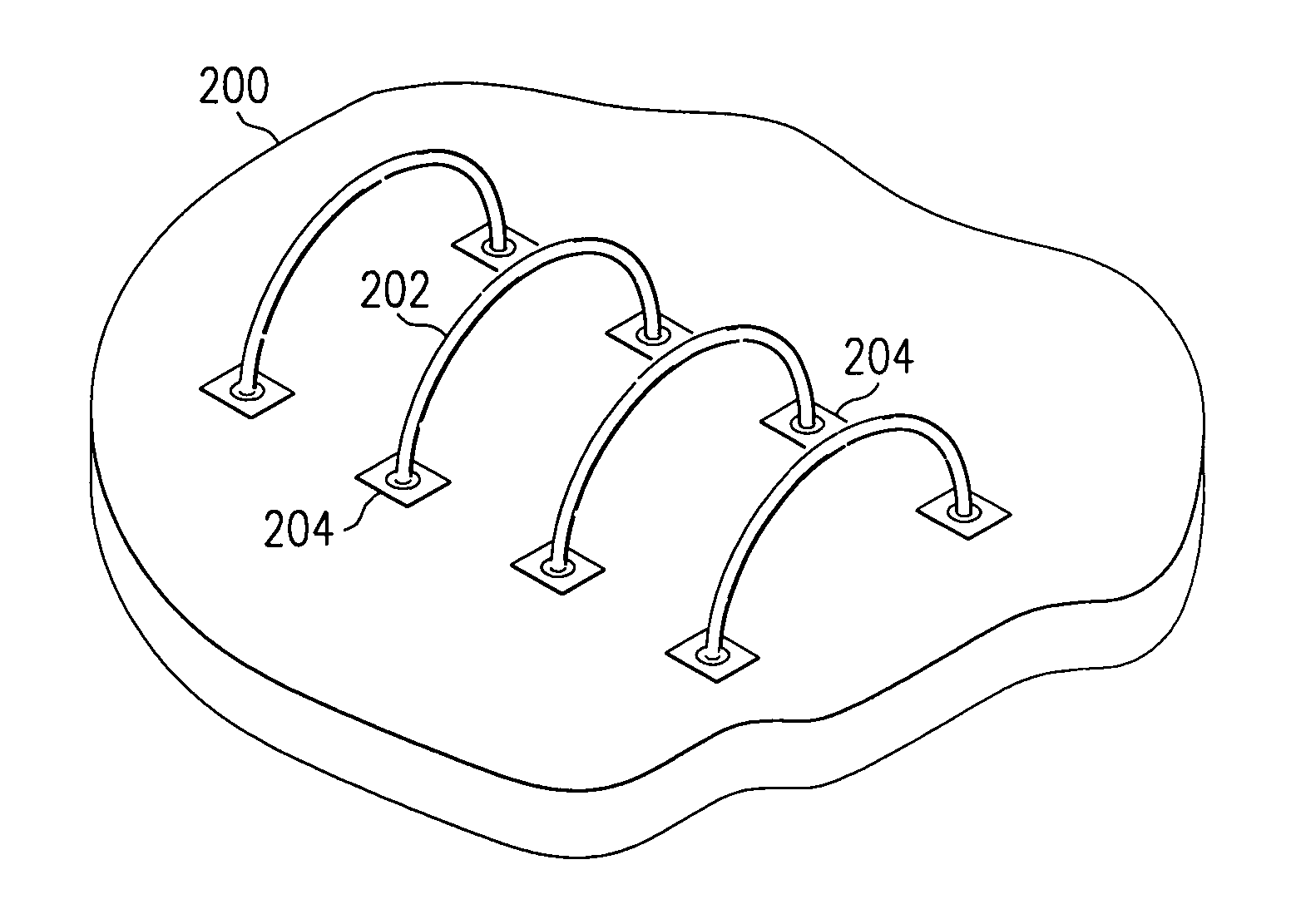
[0032]A new package feature has been developed that forms an anchor to secure getters and other materials within a package. The anchor overcomes the limitations of the prior art which required the getter or other material to be adhered to the inside of the package prior to the application of a lubricant. When an anchor according to an embodiment of the present invention is used, the lubricant may be applied prior to, or simultaneously with, the getter.

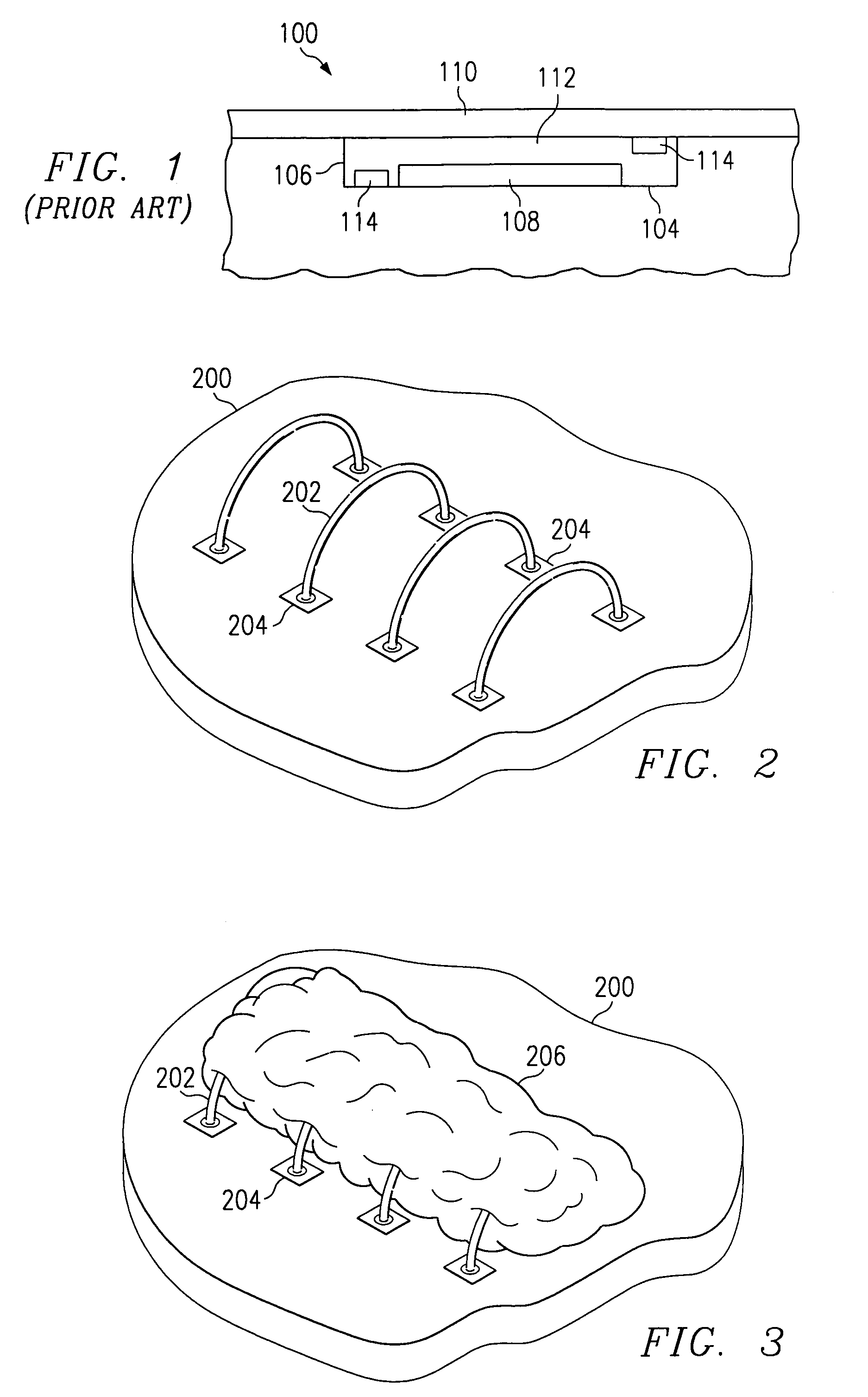
[0033]FIG. 1 is a cross section side view of a semiconductor or micromechanical package 100 of the prior art showing the location of a getter within the package. In FIG. 1, a package substrate 102 has an interior floor 104 and interior walls 106. The package substrate 102 typically is formed of layers of ceramic. The layers of ceramic include metalization regions (not shown) that provide electrical connection between the device 108 contained in the package and circuitry external to the package. After patterning the metalization on the ...


PUM


Abstract

An anchor to hold getter materials in place within a micromechanical device package substrate. First and second cavity faces define an anchor cavity and mechanically retain a getter away from a region holding the micromechanical device. The getter anchor may be formed in a substrate comprised of at least three layers. The layers form a cavity in the substrate with a wide bottom portion—formed in the middle layer and a relatively narrower top portion—formed by the top layer. The narrow portion helps to retain the getter in the cavity by creating a mechanical lock on the wide portion of getter in the bottom of the cavity.

Description

CROSS-REFERENCE TO RELATED APPLICATIONS[0001]This application claims priority under 35 USC §119(e)(1) of provisional application Ser. No. 60 / 250,913 filed Nov. 30, 2000.[0002]The following patents and / or commonly assigned patent applications are hereby incorporated herein by reference:[0003]Patent No.Filing DateIssue DateTitle5,061,049Sep. 13, 1990Oct. 29, 1991Spatial Light Modulatorand Method5,583,688Dec. 21, 1993Dec. 10, 1996Multi-Level DigitalMicromirror DeviceFIELD OF THE INVENTION[0004]This invention relates to the field of micro-electromechanical systems (MEMS), more particularly to methods of attaching getters in packages containing lubrication for the MEMS device.BACKGROUND OF THE INVENTION[0005]Micromechanical devices are small structures typically fabricated on a semiconductor wafer using techniques such as optical lithography, doping, metal sputtering, oxide deposition, and plasma etching which have been developed for the fabrication of integrated circuits.[0006]Micromirr...

Claims


Application Information

Patent Timeline
IPC IPC(8): H01L23/20H01L23/02H03J3/20H01L29/82B81B7/00H01L23/13H01L23/26
CPCB81B7/0038H01L23/13H01L23/26H01L24/48H01L2924/01033G02B26/0833H01L24/45H01L2224/45144H01L2224/48091H01L2224/48227H01L2224/484H01L2224/48599H01L2224/48997H01L2224/8592H01L2924/01005H01L2924/01006H01L2924/01079H01L2924/14H01L2924/15153H01L2924/15165H01L2924/15787H01L2924/16195H04N5/7458B81B2203/0307H01L2924/00014H01L2224/85399H01L2224/05599
Inventor ROBBINS, ROGER A.LIU, JWEI WIENSMITH, JACK C.FISHER, EDWARD CARLHOLTON, JOYCE WONG
Owner TEXAS INSTR INC
Why Eureka
Try Eureka