Motor control apparatus operable in fail-safe mode

Active Publication Date: 2006-01-31
DENSO CORP
View PDF15 Cites 35 Cited by
  • Summary
  • Abstract
  • Description
  • Claims
  • Application Information

AI Technical Summary

Benefits of technology

[0007]It is a first object of the present invention to provide a motor control apparatus which can rotate a rotor to a position that is as close to a t

Problems solved by technology

Therefore, if the rotation of the rotor is stopped for a certain reason and the encoder comes to output no pulse signal, a problem occurs that the current supply phase can no longer be switched and hence the rotor cannot be rotated to the target position.
However, this configuration requires two systems of drive coils and hence is high in manufacturing cost.
In addition, where a feedback control is performed by usi

Method used


Image

  • Motor control apparatus operable in fail-safe mode
  • Motor control apparatus operable in fail-safe mode
  • Motor control apparatus operable in fail-safe mode

Examples


first embodiment

[0055](First Embodiment)

[0056]A first embodiment in which the present invention is applied to a position switching device of an automatic transmission of a vehicle will be described with reference to FIGS. 1–48.

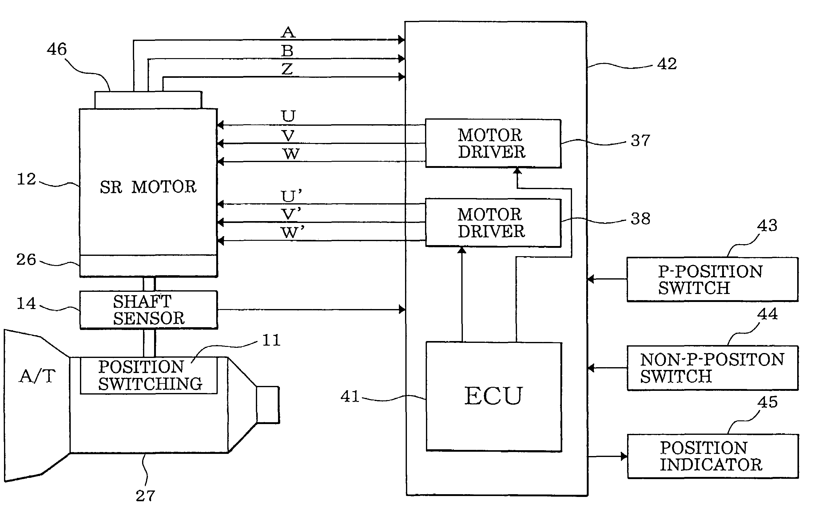
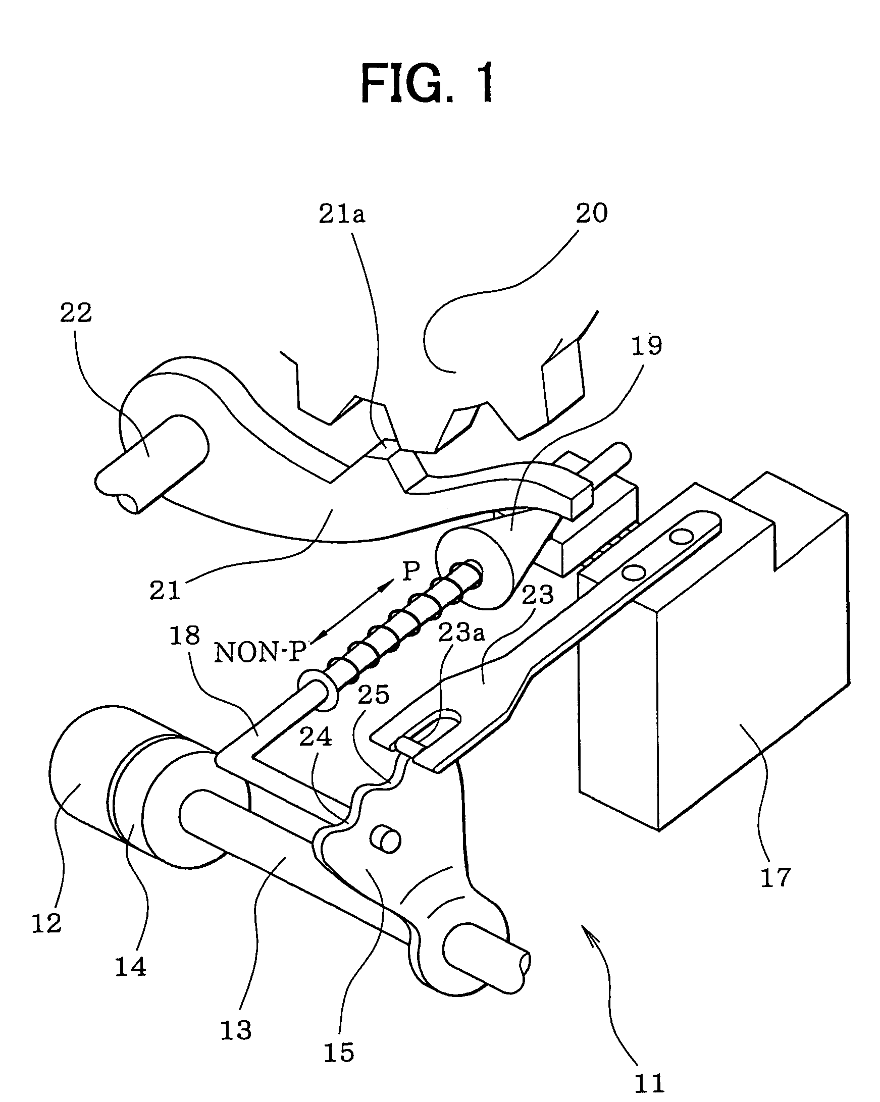
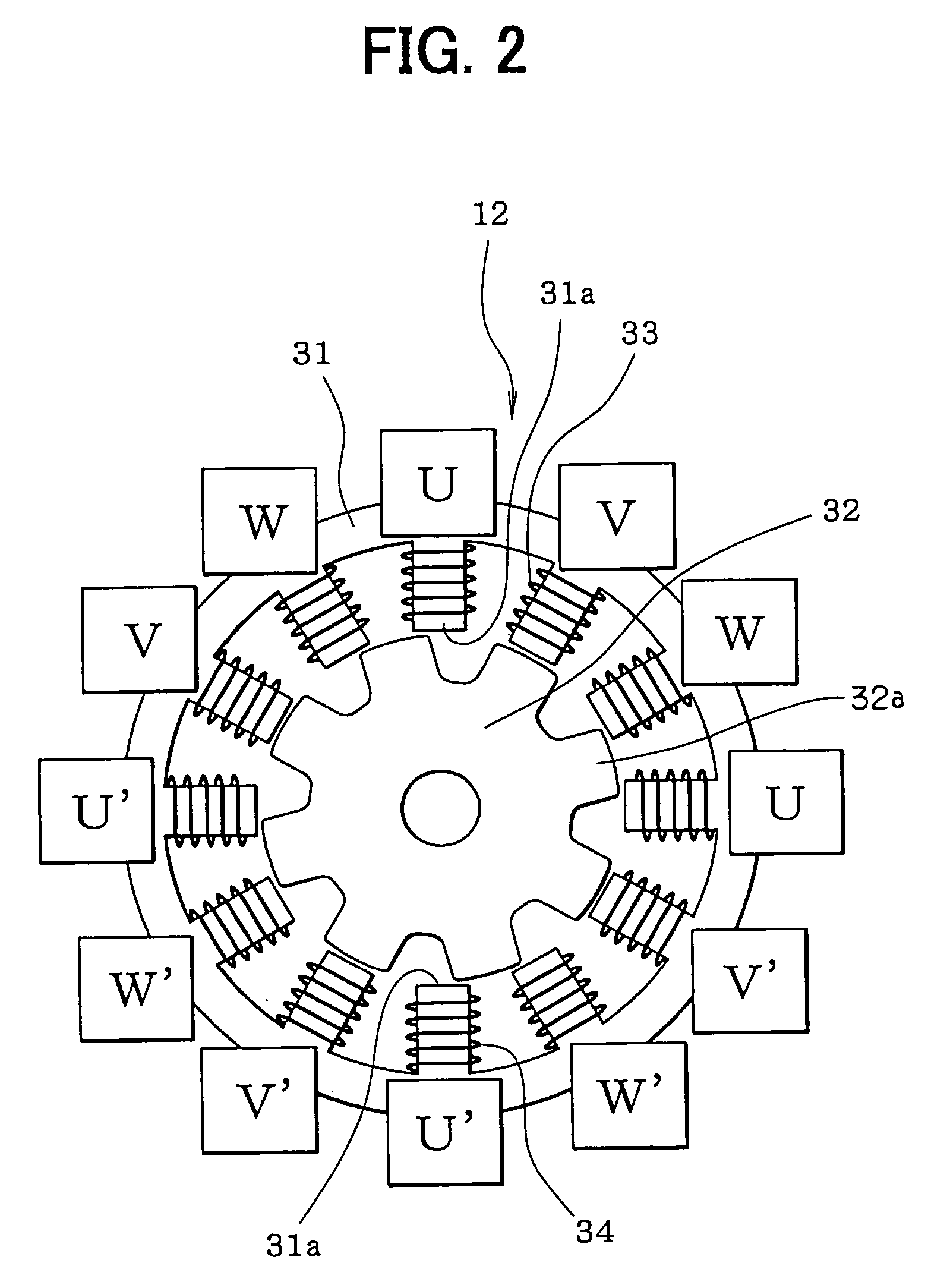
[0057]Referring first to FIG. 1, a position switching mechanism 11 is indicated with numeral 11. A motor 12 as a drive source of the position switching mechanism 11 is a switched reluctance motor, for example, incorporates a speed-reducing mechanism 26 (FIG. 4), and is equipped with an output shaft sensor 14 for detecting a rotation position of an output shaft 13 of the speed-reducing mechanism 26. A detent lever 15 is fixed to the output shaft 13.

[0058]An L-shaped parking rod 18 is fixed to the detent lever 15. A conical body 19 that is provided at the tip of the parking rod 18 is in contact with a lock lever 21. The lock lever 21 is moved in the vertical direction in accordance with the position of the conical body 19 and thereby locks or unlocks a parking gear 20. The park...

second embodiment

[0191](Second Embodiment)

[0192]In a second embodiment, if a disconnection is detected in the windings of one phase when a feedback control is started, the first current supply phase is set to one of the other two phases in which no disconnection is detected. More specifically, a phase that follows the disconnection-detected phase (hereinafter referred to as “disconnection phase”) in the order of current supply phase switching is set as the first current supply phase. This measure maximizes the number of times of current supply phase switching (i.e., the number of times of energization) that is performed until the disconnection-detected phase is selected as a current supply phase after a feedback control being started. Therefore, the rotation speed of the rotor 32 and hence its inertia is increased sufficiently by a time when the disconnection-detected phase will be selected as a current supply phase, whereby the feedback control can be performed reliably.

[0193]Further, in this embod...

third embodiment

[0249](Third Embodiment)

[0250]In the second embodiment, whether a disconnection exists in the windings 33 of each phase is determined by detecting a voltage level of the current supply line of each phase (i.e., a voltage level of the connecting point of the two resistors 61 and 62 of the disconnection detection circuit 60 of each phase). In contrast, in a third embodiment shown in FIGS. 43 and 44, whether a disconnection exists in the windings 33 of each phase is determined by detecting, with a current sensor 63, an energization current flowing through the current supply line of each phase.

[0251]As shown in FIG. 43, the neutral point of the drive coil 35 is connected to the negative pole of the battery 40 and one end of the windings 33 of each phase is connected to the positive pole of the battery 40 via a corresponding switching element 39 of the motor driver 37. Current supply to the windings 33 of each phase is turned on or off by turning on or off the corresponding switching ele...


PUM


Abstract

In a motor feedback control, the current supply phase is set on the basis of the encoder count of an encoder and the current supply phase is also set on the basis of the encoder count by time-synchronous processing. In the feedback control, a maximum value or a minimum value of encoder counts is stored with updating. The rotation reversing is determined by comparing the present encoder count with the maximum value or the minimum value. If reversing is detected, the reverse rotation is stopped by fixing the current supply phase. If a disconnection is detected in windings of one phase in starting a motor feedback control, one of the other two phases for which no disconnection is detected is set to the first current supply phase.

Description

CROSS REFERENCE TO RELATED APPLICATION[0001]This application is based on and incorporates herein by reference Japanese Patent Applications No. 2002-293269 filed on Oct. 7, 2002 and No. 2003-74824 filed on Mar. 19, 2003.FIELD OF THE INVENTION[0002]The present invention relates to a motor control apparatus for rotationally driving (rotating) the rotor of a motor to a target position by detecting the rotation position of the rotor and sequentially switching the current supply phase of the motor.BACKGROUND OF THE INVENTION[0003]Brushless motors such as switched reluctance motors are increasingly demanded because they are inexpensive and simple in structure. Those motors incorporate an encoder for outputting a pulse signal in synchronism with the rotation of the rotor, which is rotated by sequentially switching the current supply phase by counting pulses of a pulse signal of the encoder and detecting the rotation position of the rotor on the basis of the encoder count. Since it is possib...

Claims


Application Information

Patent Timeline
IPC IPC(8): H02P3/18H02P3/00H02P1/46H02P6/16H02P8/42H02P25/08
CPCH02P6/16H02P25/08H02P8/42
Inventor KAMIO, SHIGERUNAKAI, YASUHIRO
Owner DENSO CORP
Why Eureka
Try Eureka