
Attitude determination system using null-steered array

a technology of arrays and positions, applied in direction finders, instruments, measurement devices, etc., can solve problems such as prone to errors in measurements, hindering the use of these devices, and prone to errors in geo-magnetic sensors

Active Publication Date: 2006-01-31
NOVATEL INC
View PDF12 Cites 6 Cited by
  • Summary
  • Abstract
  • Description
  • Claims
  • Application Information

AI Technical Summary

Problems solved by technology

Geo-magnetic sensors are susceptible to errors from locally generated magnetic fields (from nearby electronics) and from nearby magnetic objects.
Such limitations have hindered the use of these devices.
Such measurements are prone to errors due to multi-path effects even though there are antennas and algorithms to counter these effects.
But, such antennas and algorithms are costly and typically block out low elevation satellites thus reducing the number of satellites used for the measurements.
Another limitation of prior art techniques using differential phase GNSS measurements is that long baselines (long times) are needed for accurate headings, but longer baselines make acquisition more difficult, and shorter baselines reduce accuracy.
However, both of these inventions are subject to the limitations described above.

Method used


Image

  • Attitude determination system using null-steered array
  • Attitude determination system using null-steered array
  • Attitude determination system using null-steered array

Examples


Embodiment Construction

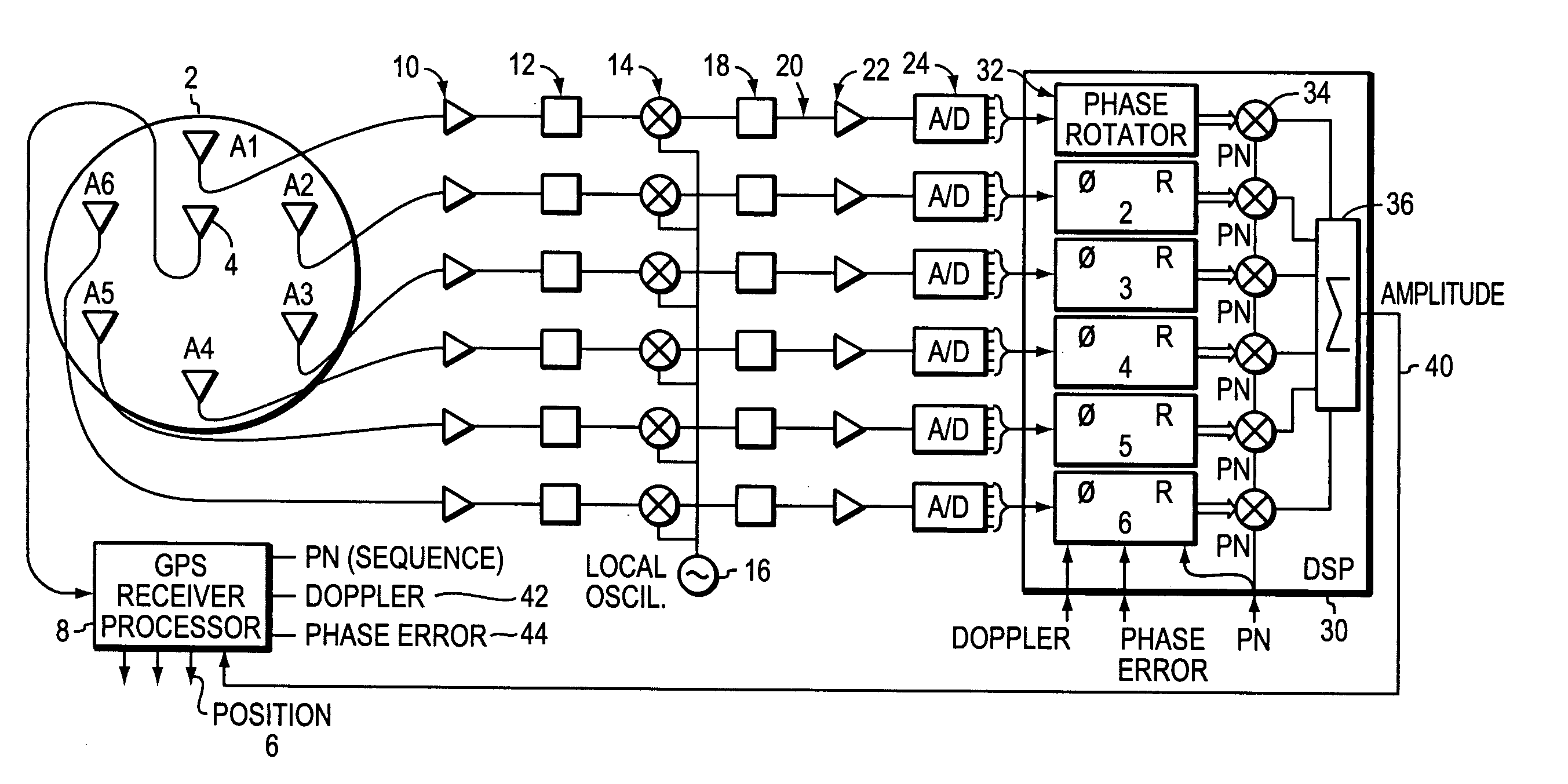
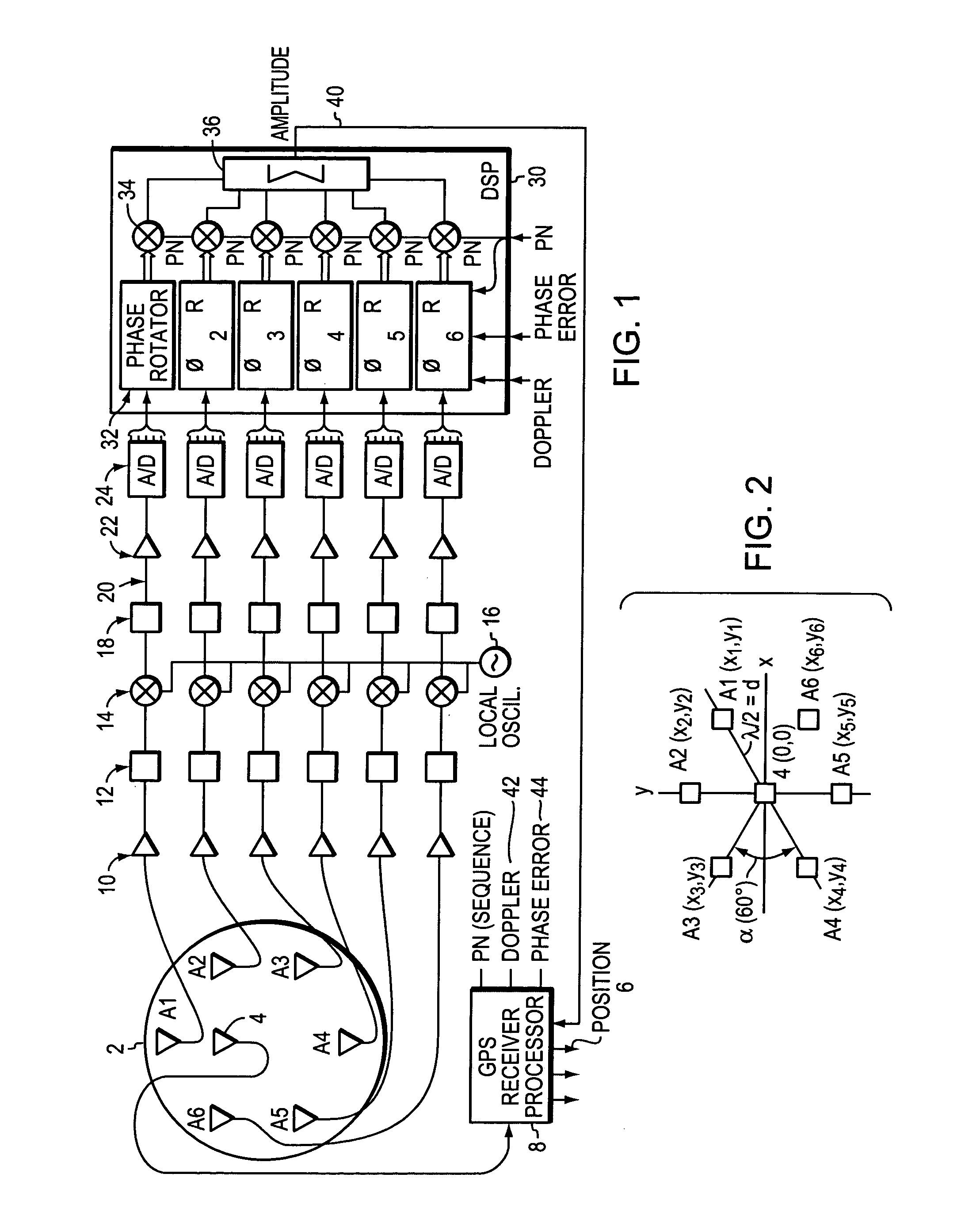
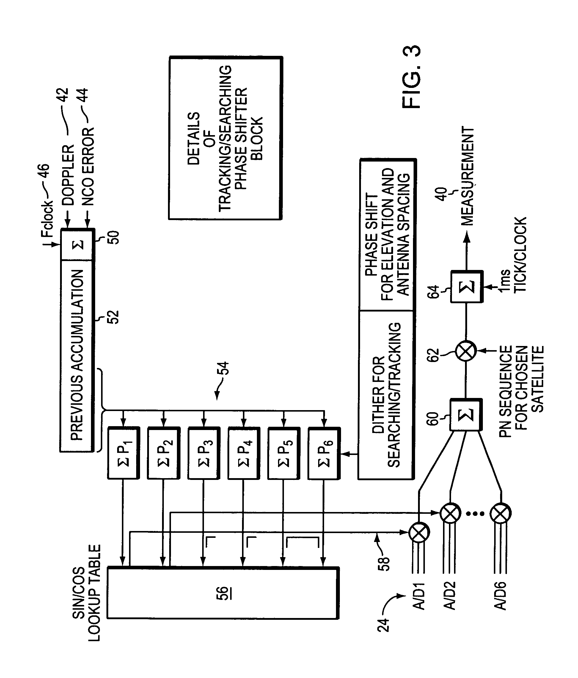
[0019]FIG. 1 is a block diagram schematic of a preferred electronic system and a seven antenna array 2 with a center antenna 4 that tracks all available GNSS satellites. GNSS systems are most familiar, but other satellite positioning systems may be used. A preferred antenna array is described in U.S. patent, mentioned above, U.S. Pat. No. 6,466,177 to Kunysz, which has been incorporated herein by reference. However, other arrays with fewer as antennas may be used to advantage as described below. In the seven antenna array, the center antenna tracks the array's position 6 on the Earth as commonly performed by the GNSS receiver 8.

[0020]Although this illustrative example discusses a satellite as a radiating source, other sources may be used to advantage within the present invention. Those other sources must have known locations, and may include television broadcasting towers, cell phone towers, or virtually any other tower based radiating source.

[0021]Still referring to FIG. 1, each an...


PUM


Abstract

Apparatus and process for determining the position and heading or attitude of an antenna array are described based on radiating sources, preferably GNSS or other such satellite positioning systems. An optimum satellite is selected and the antenna array is “null steered” by combining the phase of the received signals to calculate a null or null angle that points toward the optimum satellite. The null will determine angle for elevation toward the optimum satellite and azimuth or heading. The heading is the azimuth of the (which may be actual or calculated) projection of the null vector to the satellite onto the Earth's surface. The actual location on Earth of the antenna array can be found and the antenna array azimuth with respect to the satellite can be determined. The null angle may be measured more precisely by dithering on either side to average out noise and then averaging the angle deviations to calculate the null angle. If the attitude of the antenna array with respect to the Earth's surface is desired, a null vector to a second satellite may be generated and the intersection of the two nulls will allow the attitude of the antenna array, with respect to one or both of the satellites, to be determined. The difference between the measured attitude of the antenna array with respect to the null vector and the calculated attitude of the satellite from the GNSS signals, is the attitude of the array with respect to the Earth's surface. All viewable satellites may be used, tracked, and nulls determined for each, and many antennas if in a known pattern relative to each other can be used to make the determinations more accurate and reliable.

Description

BACKGROUND OF THE INVENTION[0001]1. Field of the Invention[0002]The present invention relates to determining navigation heading or attitude using a satellite based positioning system and antenna array.[0003]2. Background Information[0004]Commonly used attitude determination apparatus and methods include use of geomagnetic sensors, gyroscopic sensors or phase differences of signals received from multiple satellites of the Global Navigation Satellite System (GNSS) or other similar systems.[0005]Geo-magnetic sensors are susceptible to errors from locally generated magnetic fields (from nearby electronics) and from nearby magnetic objects. Additionally, local earth magnetic fields must be mapped and available to the user. Gyroscopic sensors drift and must be re-calibrated regularly. Such limitations have hindered the use of these devices.[0006]GNSS systems and techniques, including differential techniques, are now commonplace and as background are only briefly described herein. Signals ...

Claims


Application Information

Patent Timeline
Patent Type & Authority Patents(United States)
IPC IPC(8): G01S5/04G01S19/46G01S3/04G01S3/40G01S3/46G01S5/02G01S5/14
CPCG01S19/54G01S3/40
Inventor FELLER, WALTER J.
Owner NOVATEL INC
Learn More