Manufacturing cell using tooling apparatus

a tooling apparatus and tooling technology, applied in the direction of turning machines, turning machine accessories, supporters, etc., can solve the problems of significant setup time, significant amount of production time lost in tooling changeover, and trial and error process

Inactive Publication Date: 2006-02-07
GENERAL ELECTRIC CO
View PDF62 Cites 24 Cited by
  • Summary
  • Abstract
  • Description
  • Claims
  • Application Information

AI Technical Summary

Problems solved by technology

The alignment of the dedicated tooling and the workpiece it holds to the metalworking machine must be exact, and often requires significant setup time to ensure proper alignment with the metalworking machine.
Achieving such alignment is a trial-and-error process, generally requiring repeated steps of tapping the tooling to move it a small distance, tightening the bolts used to secure it in place, and then checking the alignment using dial indicators or the like.
The critical nature of this process typically requires attention by the most highly skilled workers in the manufacturing facility.
When a metalworking facility needs to machine a variety of members of a workpiece family, there can be significant amounts of production time lost in tooling changeover, in disassembling tooling used on the first workpiece, retrieving the dedicated tooling for the next workpiece, and then installing and aligning the retrieved dedicated tooling, etc.
Changing the tooling from that required for one workpiece to that required for another similar workpiece is frequently a major factor in the cost for operating a metalworking facility, particularly when business conditions in the industry can necessitate small production lot sizes.
Because each set of dedicated tooling must accept and secure the workpiece in generally two or more places for proper positioning and alignment, these dedicated tools can be complex and expensive.
During a tooling changeover, it is necessary to change the tooling for each metalworking machine, but in addition, all other machines in the cell are typically idle while the tooling on any one machine is being changed.
The various types of conventional tooling for securing the workpiece to the table typically do not provide rapid changeover from one workpiece to the next.
Conventional tooling can require substantial disassembly of the tooling to make such a changeover, and substantial time to change the tooling from that used with one member of a family of workpieces to that used with another family member.
Each of these factors typically leads to extensive commitment of time by highly skilled technicians to secure the next workpiece, or the next set of tooling, to the table.
Whenever a metalworking machine is idled to change either a workpiece or tooling, it cannot perform its intended metalworking function.

Method used


Image

  • Manufacturing cell using tooling apparatus
  • Manufacturing cell using tooling apparatus
  • Manufacturing cell using tooling apparatus

Examples


Embodiment Construction

Definitions

[0041]As used herein, the phrase “metalworking machine” refers to any machine for the cutting, forming, joining or otherwise processing of a metallic workpiece. The term can include, but is not limited to, a milling machine, a planer, a shaper, a drill press, a vertical turret lathe, a grinder, EDM and ECM machines, a broaching machine, a bending brake, a stamping press, and a welding apparatus. In a broad context, the term can also include such diverse forms of equipment as a lathe or a die casting machine.

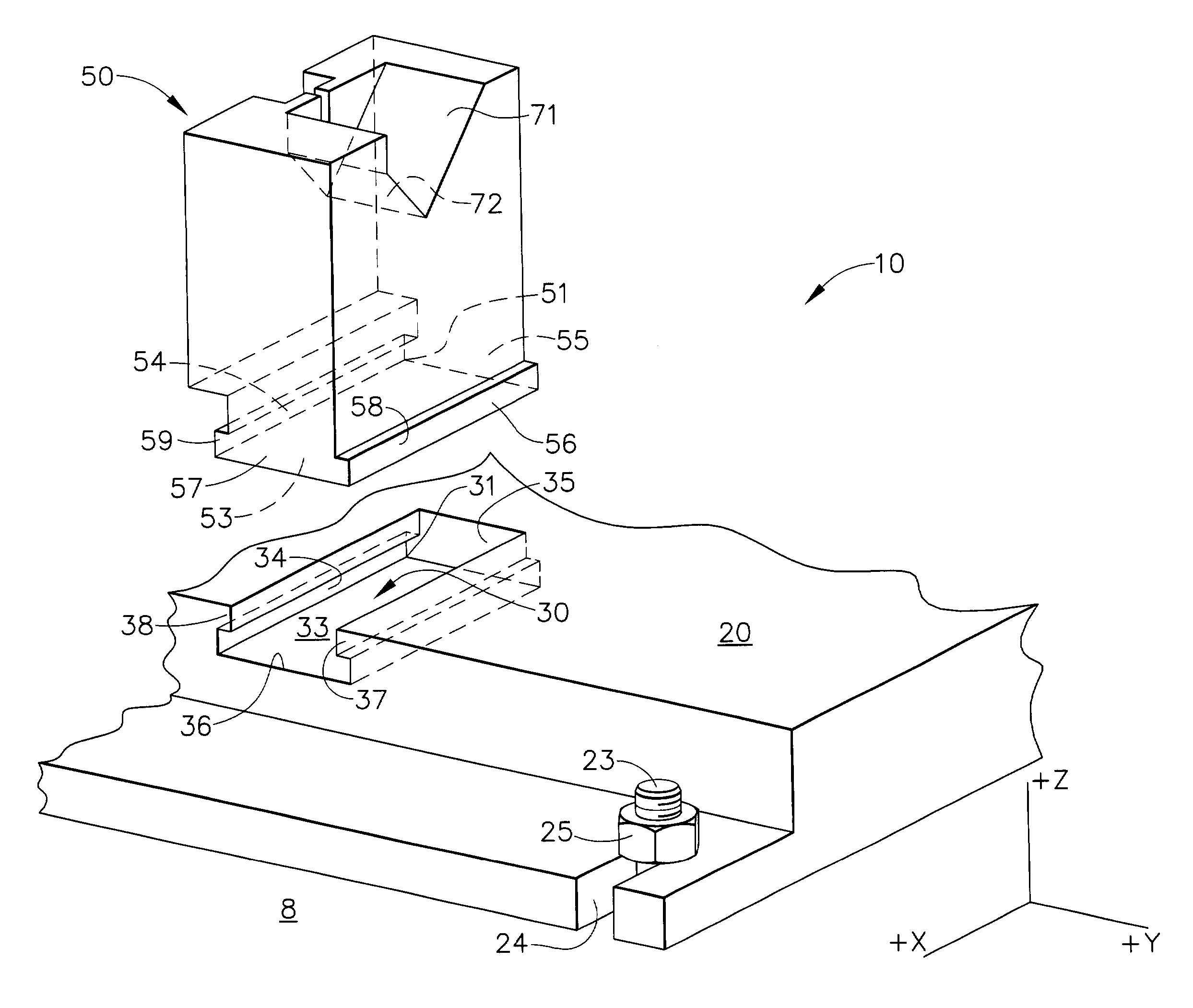
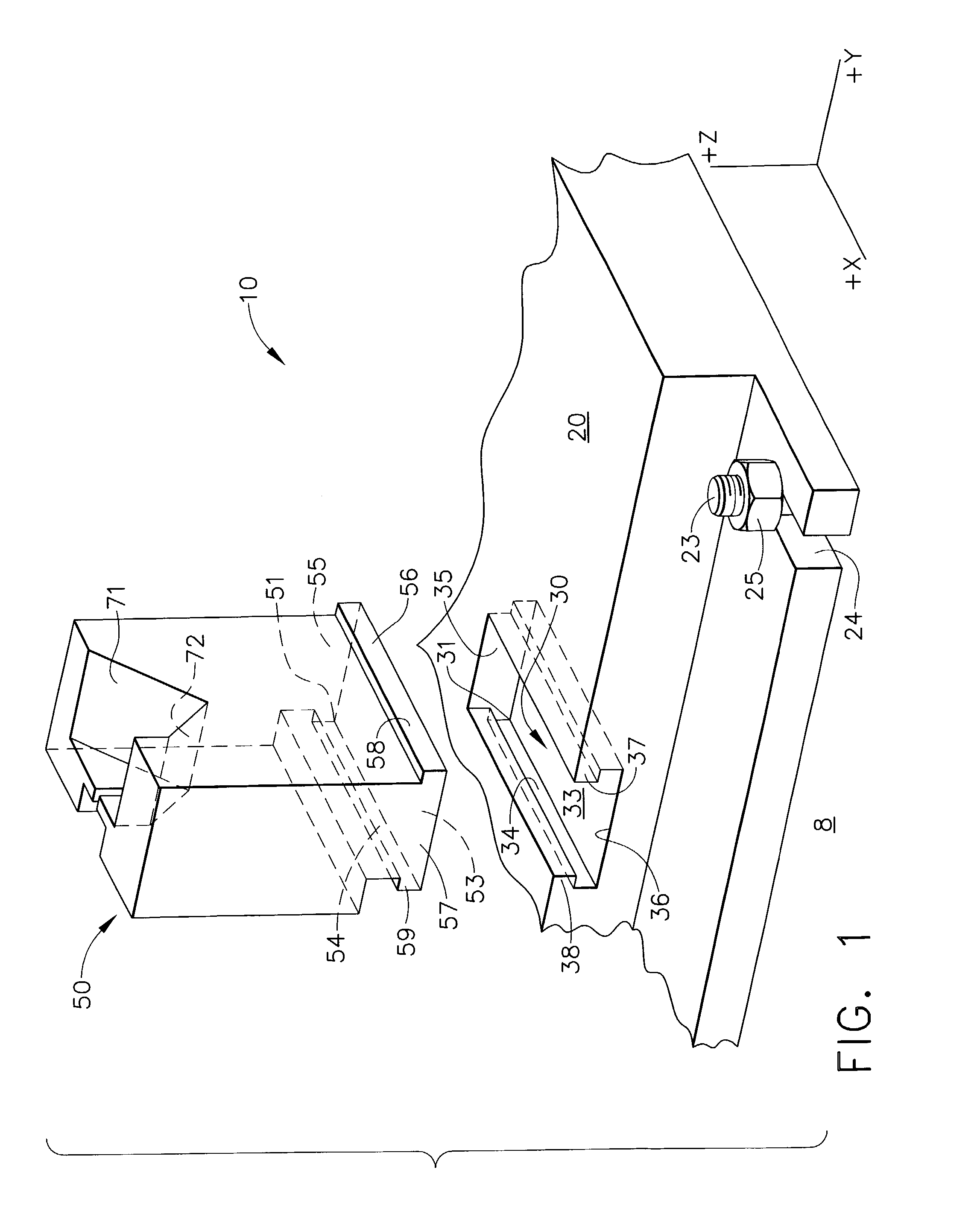
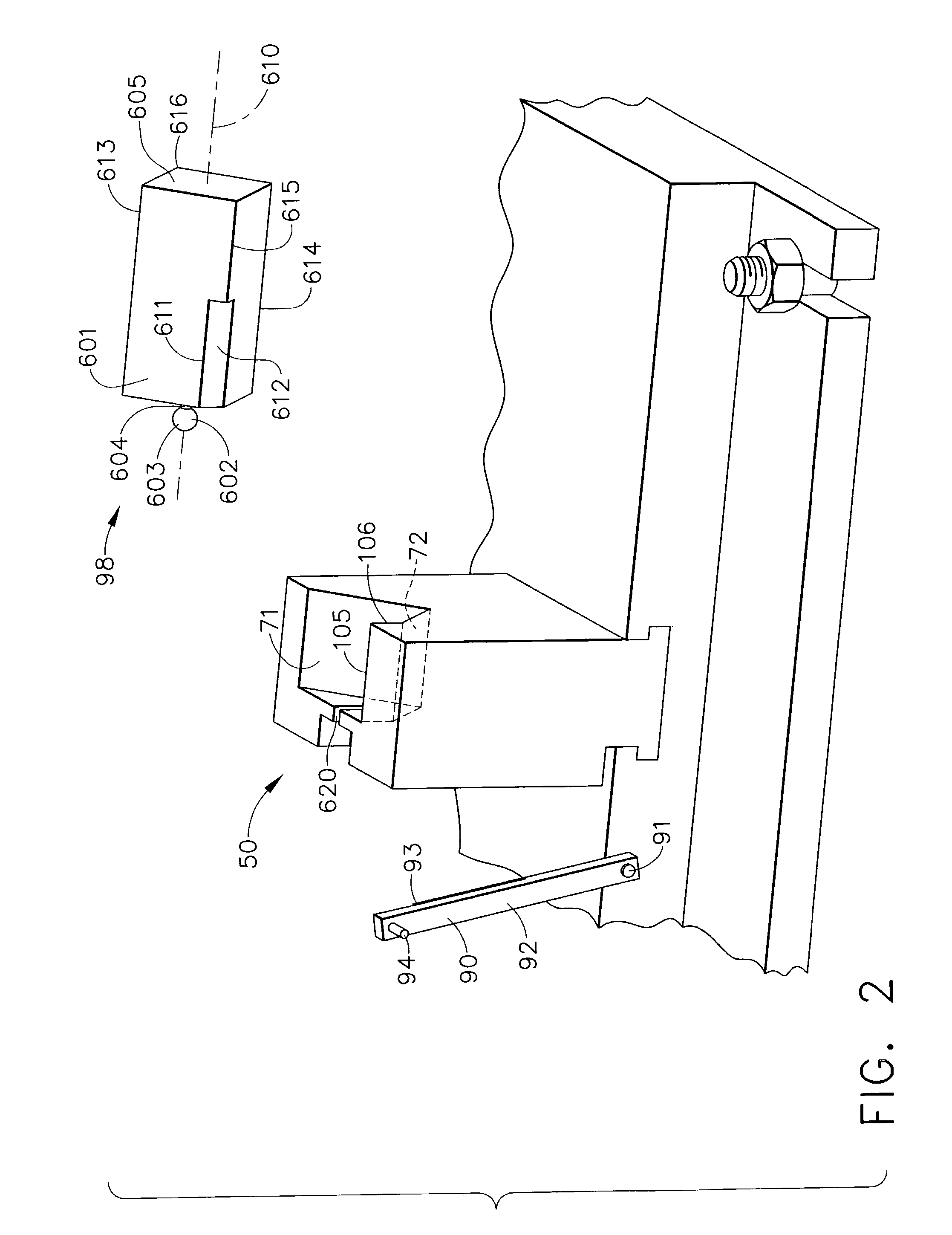
[0042]As used herein, the term “tooling” refers to an apparatus for holding and supporting a workpiece while it is being cut, formed, joined or otherwise processed by a metalworking machine.

[0043]As used herein, the term “tool” refers to an apparatus used by a metalworking machine to cut, form, join or otherwise process a workpiece.

[0044]As used herein, the phrase “manufacturing cell” refers to a plurality of metalworking machines, clustered together in close proximity...


PUM

PropertyMeasurementUnit
angleaaaaaaaaaa
forceaaaaaaaaaa
sizeaaaaaaaaaa

Abstract

A manufacturing cell having a plurality of work stations, where at least one of the work station comprises a metalworking machine, and where at least one metalworking machine is provided with a modular tooling apparatus. The modular tooling apparatus consists of a base having one or more attachment surfaces, and one or more inserts that can be inserted semi-permanently to the attachment surfaces. The attachment surface is typically a pocket in the surface of the base. The insert has a workpiece support feature that can support and / or secure the workpiece into the proper position and orientation for machining. The base, pockets and inserts are configured to provide a characteristic location and orientation for the workpiece relative to the base, and to the metalworking machine. The modular tooling apparatus permits machining a family of workpiece members that are related but different in detail, by inserting an insert member from the family of inserts to properly position and orient the corresponding workpiece member, without needing to change, disconnect, or move the base tooling. The invention also provides a process for performing a plurality of metalworking operations on workpieces, employing the manufacturing cell described hereinabove.

Description

CROSS-REFERENCE TO RELATED APPLICATIONS[0001]This application claims the benefit of U.S. Provisional Application No. 60 / 437,236, filed Dec. 30, 2002; U.S. Provisional Application No. 60 / 437,238, filed Dec. 30, 2002; and U.S. Provisional Application No. 60 / 437,497, filed Dec. 30, 2002.FIELD OF THE INVENTION[0002]The invention relates to the field of tooling for metalworking operations and tooling systems for metalworking operations, and in particular, to manufacturing cells comprising a plurality of metalworking operations clustered together in adjacent locations on a factory floor.BACKGROUND OF THE INVENTION[0003]The development of metalworking machines was one of the key factors in the Industrial Revolution that began around the turn of the nineteenth century. This was a class of machine that could make almost anything, including reproducing itself. Researchers in manufacturing processes soon realized that more efficient metalworking machines would reduce the manufacturing cost of ...

Claims


Application Information

Patent Timeline
Patent Type & Authority Patents(United States)
IPC IPC(8): B23P23/00B23Q3/06B23Q3/02B23Q3/10B23Q37/00B25B5/00B25B5/14F02C7/00F04D29/38
CPCB23Q3/103B23Q37/00B25B5/003B25B5/006B25B5/14Y10S269/90Y10T29/5196Y10T409/308624Y10T279/3462Y10T29/5124Y10T409/30868Y10T409/309016Y10S269/902
Inventor AHTI, ROBERT ALLANDUPUIS, CHRISTIANELMAN, LARISA ALEXANDRA
Owner GENERAL ELECTRIC CO
Why Eureka
Try Eureka