
Heater cycling for improved oil return

a technology of oil return and heat exchanger, which is applied in the direction of heat exchangers, heating apparatus, domestic cooling apparatus, etc., can solve the problems of reducing heat transfer effectiveness, compressor failure, and difficult to control the temperature of the space to be refrigerated within relatively narrow limits, so as to achieve improved oil return and maintain tight temperature control

Active Publication Date: 2006-02-07
CARRIER CORP
View PDF4 Cites 18 Cited by
  • Summary
  • Abstract
  • Description
  • Claims
  • Application Information

AI Technical Summary

Benefits of technology

The present invention provides a method for improving oil return in a refrigeration unit while maintaining tight temperature control in the refrigerated space. This is achieved by providing a refrigeration unit with a sensor for measuring an operating parameter, such as the compressor oil temperature, and a controller for turning on and off the heating element in response to the measured operating parameter. The heating element can provide heat to the refrigerated space in a pulsed on and off mode or when the operating parameter exceeds a time limit associated with a refrigerant system component that can affect the operating parameter. This method helps to improve oil return and ensures efficient refrigeration unit operation.

Problems solved by technology

This logging of oil in turn compromises oil return to the compressor and thus reduces the heat transfer effectiveness of the evaporator coil or in some instances can even lead to complete oil pump out from the compressor resulting in the compressor failure.
Unfortunately, cycling the entire refrigeration unit 10 can result in a scenario wherein it is difficult to control the temperature of the space to be refrigerated within relatively narrow bounds.
In addition, if the compressor does not run continuously there are additional cycling losses due to frequent start / stops resulting in increased power consumption.
Also compressor reliability may be compromised due to frequent start / stops.

Method used


Image

  • Heater cycling for improved oil return
  • Heater cycling for improved oil return

Examples


Embodiment Construction

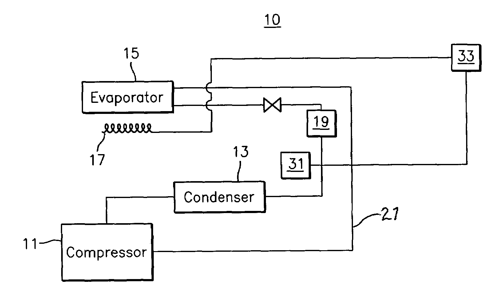
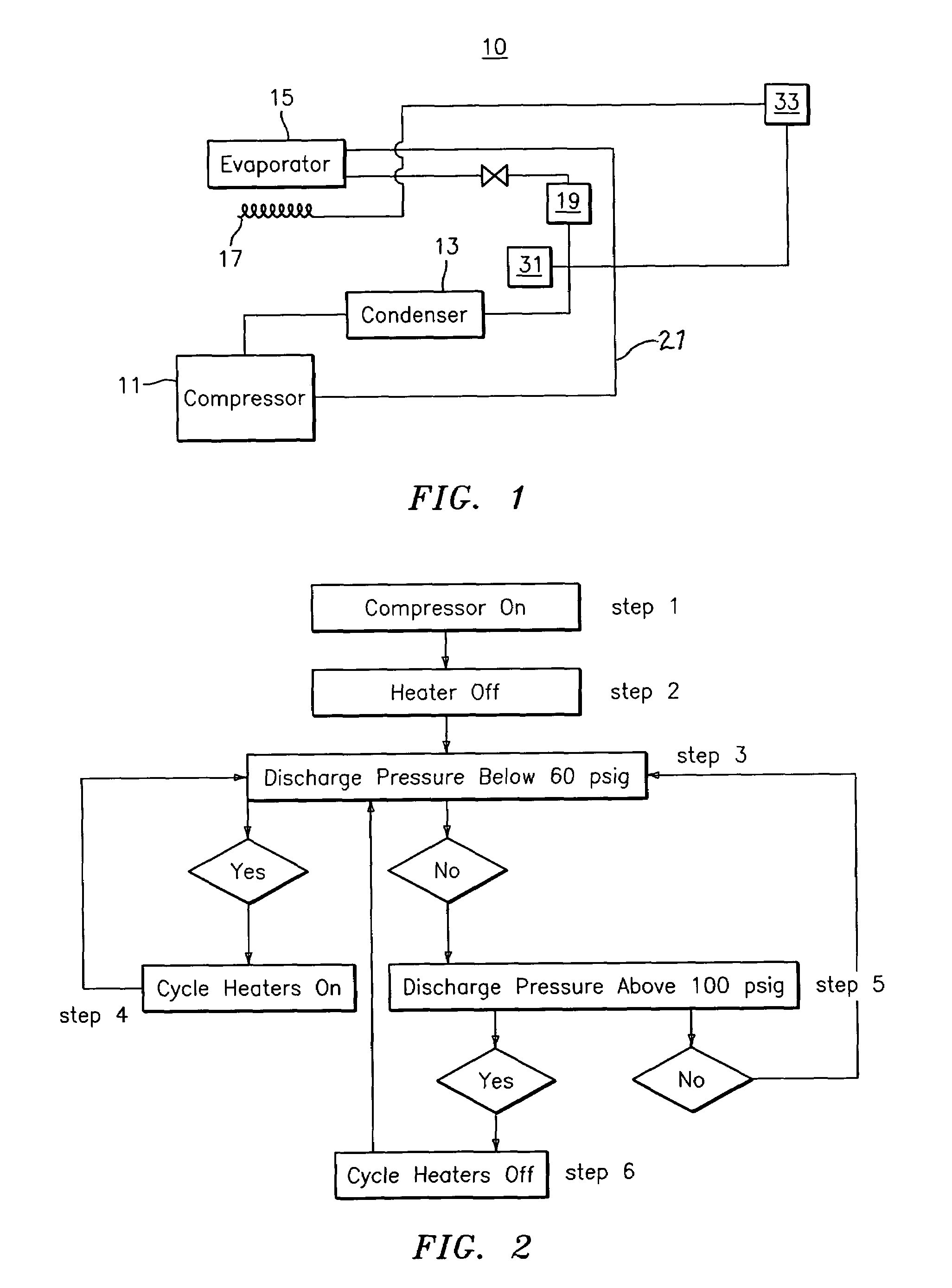
[0014]It is therefore an aspect of the present invention to provide a method for cycling the operation of heaters in proximity to a refrigeration unit 10 so as to increase refrigerant / oil mass flow through the evaporator. By turning on and off a heater 17, the refrigeration unit 10 is forced to run at a level which requires greater refrigerant / oil mass flow than would be required in the absence of the introduction of such heat. The heater is turned on and off based upon at least one continually monitored operating parameter of the refrigeration unit 10. The heating element 17 is turned on and off to maintain the value of the operating parameter between two predefined threshold levels. By cycling a heating element 17 on and off in this manner, refrigerant / oil mass flow through the evaporator 15 is maintained at a level sufficient to substantially eliminate the logging of oil in the evaporator, thereby increasing the efficiency of the evaporator 15.

[0015]With reference to FIG. 1, ther...


PUM


Abstract

A method comprises the steps of (a) providing a refrigeration unit having a refrigerated or heated space and at least one measured operating parameter, (b) providing heat to the refrigerated space when the at least one measured operating parameter exceeds a first threshold, (c) terminating provision of heat when the at least one measured operating parameter exceeds a second threshold, and repeating steps b–c when the at least one operating parameter falls below the first threshold. In using this method, the unit can be operated continuously, with substantially higher refrigerant mass flow and evaporator pressure then in the prior art. Higher refrigerant mass flow rate and higher evaporator pressure improve oil return to the compressor, thus reducing the like hood of compressor damage due to oil pump out.

Description

BACKGROUND OF THE INVENTION[0001](1) Field of the Invention[0002]The present invention relates to a method for improving oil return in a refrigeration unit.[0003](2) Description of the Related Art[0004]With reference to FIG. 1, there is illustrated a refrigeration unit 10. Typically, a refrigerant / oil mixture travels in a circuit from the compressor 11 through the condenser 13 to an expansion device 19 then to an evaporator 15 and then to suction line 21 and finally back to the compressor 11. In instances wherein an operating refrigeration unit 10 carries perishable goods at low ambient temperatures, the amount of cooling required to maintain the cargo at a given temperature is quite minimal. In such instances, the amount of refrigerant traveling through the coil of the evaporator 15 and suction line 21 is substantially reduced. Such reduction in the amount of refrigerant results in the retention and logging of oil in the evaporator. This logging of oil in turn compromises oil retur...

Claims


Application Information

Patent Timeline
Patent Type & Authority Patents(United States)
IPC IPC(8): F25B29/00F25B31/00F25B30/02
CPCF25B31/004F25B30/02Y02A40/963
Inventor LIFSON, ALEXANDERSCARCELLA, JASON
Owner CARRIER CORP
Learn More