
On-vehicle structure of fuel cell system

a fuel cell and on-vehicle technology, applied in the direction of battery/cell, jet propulsion mounting, electrochemical generator, etc., can solve the problem of excessive elevated passenger from the ground, and achieve the effect of reducing the restriction on a space for passengers

Inactive Publication Date: 2006-02-07
TOYOTA JIDOSHA KK
View PDF20 Cites 47 Cited by
  • Summary
  • Abstract
  • Description
  • Claims
  • Application Information

AI Technical Summary

Benefits of technology

[0007]The present invention is for obviating the above-mentioned problems. Therefore, it is an object of the present invention to provide a technology to alleviate restrictions on a space for passengers in an electric vehicle equipped with a fuel cell.
[0009]The motor, the fuel cell, and the control unit are arranged in the same space of the vehicle body in the electric vehicle so that any restriction on a space for passengers caused by these components is reduced. Therefore, it is easy to secure a sufficient space for passengers.
[0013]It is easy to assemble and install the motor, the fuel cell, and the power control unit according to the above-described structure.
[0015]According to the second aspect of the present invention, it is easy to assemble the motor, the fuel cell and the power control unit and to install these components in the vehicle body.

Problems solved by technology

However, the space for mounting the fuel tank, the fuel reforming device, the fuel cell, and the second cell is relatively narrow since each component is arranged under the floor of the vehicle.
Furthermore, the passenger is excessively elevated from the ground due to the required space for these components.

Method used


Image

  • On-vehicle structure of fuel cell system
  • On-vehicle structure of fuel cell system
  • On-vehicle structure of fuel cell system

Examples


Embodiment Construction

[0022]The following explains the aspects of the present invention according to a preferred embodiment.

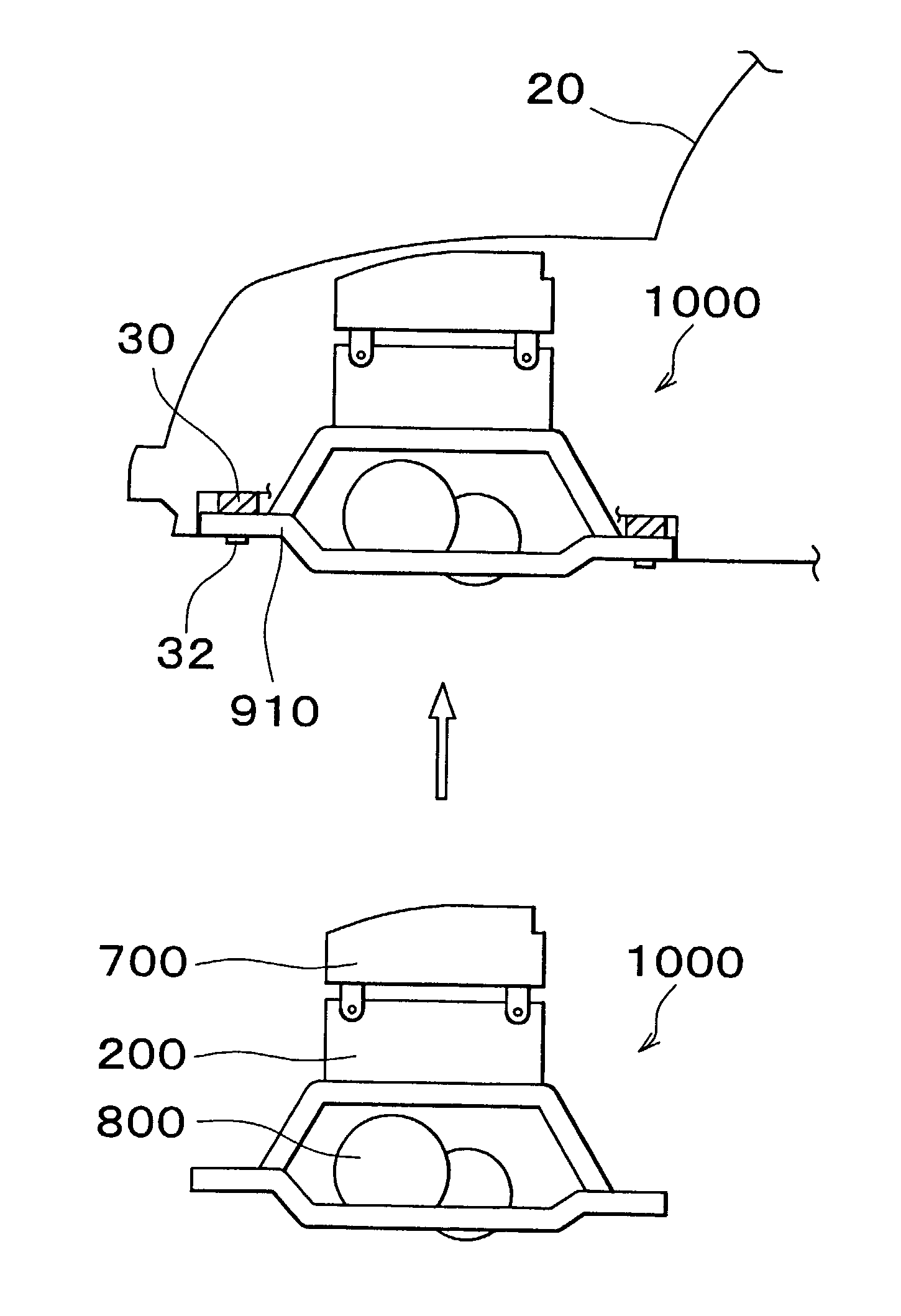
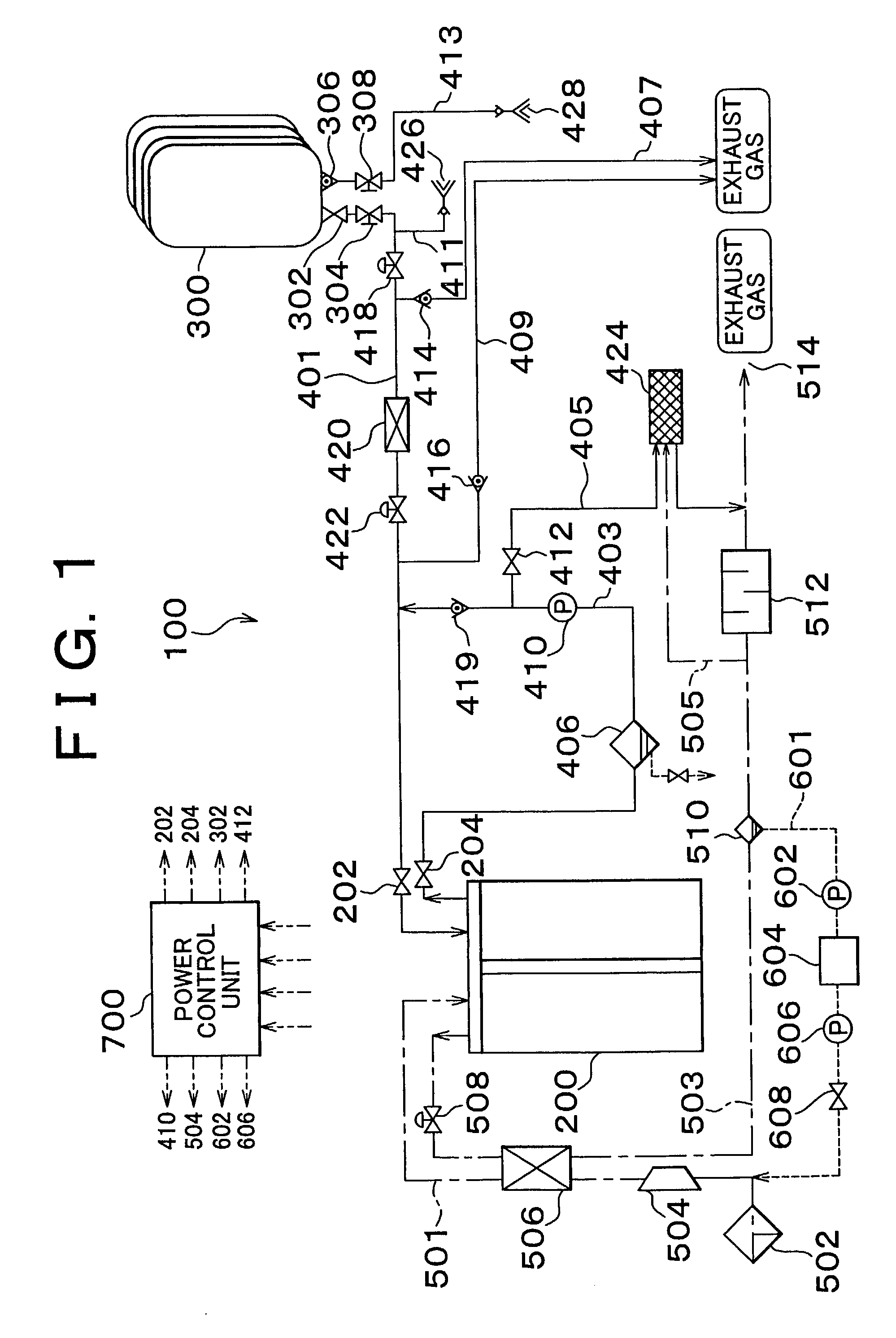
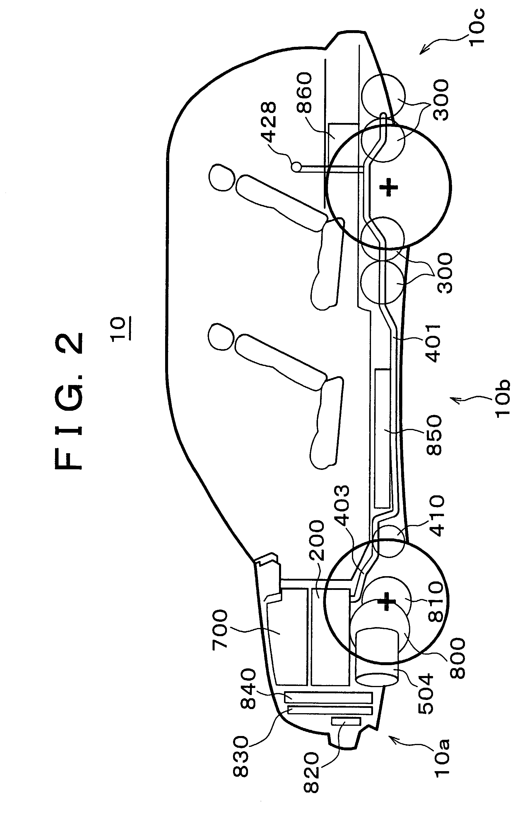
[0023]Referring to FIG. 1, a fuel cell system 100 in a vehicle includes a fuel cell 200 which is supplied with hydrogen gas to generate power and a high-pressure hydrogen gas tank 300 which supplies hydrogen gas to the fuel cell 200.

[0024]The fuel cell 200 is supplied with oxidized gas containing oxygen, such as air, along with hydrogen gas containing hydrogen, and causes the electric-chemical reactions shown as the reaction formulas below, at a hydrogen electrode and an oxygen electrode, to generate power.

[0025]In other words, hydrogen gas is supplied to the hydrogen electrode and oxygen gas is supplied to the oxygen electrode. The reaction (1) is caused on the side of the hydrogen electrode and the reaction (2) is caused on the side of the oxygen electrode. In the entire fuel cell, the reaction (3) is caused.

H2→2H++2e−  (1)

2H++2e−+(1 / 2)O2→H2O  (2)

H2+(1 / 2)O2→H2O  (3)

[0026]When the ...


PUM


Abstract

A motor for driving an axle shaft of a vehicle, a fuel cell, and a power control unit are arranged in the same space of a vehicle body in an electric vehicle. The motor is mounted on a suspension frame. The fuel cell and power control unit are mounted on a FC frame provided on the suspension frame.

Description

INCORPORATION BY REFERENCE[0001]The disclosure of Japanese Patent Application No 2001-181696 filed on Jun. 15, 2001 including the specification, drawings and abstract is incorporated herein by reference in its entirety.BACKGROUND OF THE INVENTION[0002]1. Field of the Invention[0003]The present invention relates to a manner of arranging components in an electric vehicle equipped with a fuel cell.[0004]2. Description of the Related Art[0005]As a related art of the present invention, an arranging of components in an electric vehicle was disclosed in a Japanese Patent Application Laid-Open Publication No. 2001-113960. According to this related art, a fuel tank, a fuel reforming device, a fuel cell, and a second fuel cell are arranged under a floor of the vehicle along the front and rear direction of a vehicle body in this order. The above-described structure is intended to achieve an effective arrangement of the components without excessively reducing the space for passengers and trunk ...

Claims


Application Information

Patent Timeline
IPC IPC(8): B60K6/04B60K1/04B60K15/063B60L11/18H01M8/00
CPCB60K1/04B60L11/1896B60K15/063B60K2015/0638Y10S903/908Y02T90/34Y10S903/951B60L50/71Y02T90/40
Inventor MIZUNO, MINOBU
Owner TOYOTA JIDOSHA KK
Features
  • Generate Ideas
  • Intellectual Property
  • Life Sciences
  • Materials
  • Tech Scout
  • Unparalleled Data Quality
  • Higher Quality Content
  • 60% Fewer Hallucinations
Learn More