Load torque blocking device

a technology of load torque and blocking device, which is applied in the direction of interengaging clutches, motor/generator/converter stoppers, dynamo-electric converter control, etc., can solve the problems of increased heating at high rpm, poor efficiency, and high frictional losses, so as to improve the efficiency of such a system and improve the overall degree of system efficiency , the effect of cost saving

Inactive Publication Date: 2006-02-07
ROBERT BOSCH GMBH
View PDF13 Cites 2 Cited by
  • Summary
  • Abstract
  • Description
  • Claims
  • Application Information

AI Technical Summary

Benefits of technology

[0007]The load torque lock, in accordance with the invention, has the advantage that the occurrence of centrifugal forces on the clamping bodies is avoided for the most part by displacing the mass center of gravity of the clamping bodies to the area of the axis of rotation, which in turn results in reliable avoidance over the entire rpm range of centrifugal-force-induced swiveling of the locking bodies and locking of the drive load that is thereby triggered. This results in a further advantage that this type of load torque lock can also be used preferably for high speed driving mechanisms such as electric motors that drive adjusters or components that move back and forth.
[0010]A quick and effective clamping or releasing of the locking disk on the locking ring fixed to the housing is achieved by slightly swiveling the locking disk so that the locking disk features at least two locking means on different radii and offset from one another around an angle in the circumferential direction, of which the one locking means cooperates with the outside of at least one locking ring fixed to the housing and the other locking means cooperates with its inside.
[0011]In order to counteract any inclination of the locking disk when the load torque lock is responding and to avoid an initial axial springiness of the locking disk, it is proposed that on both front sides of the locking disk two aligned locking means are each arranged laterally reversed, each of which cooperate with one of two locking rings arranged fixed to the housing on both sides of the locking disk. The locking means in this connection are embodied in a simple and reliable manner as clamping bolts projecting from the front side of the locking disk on both sides parallel to the axis of rotation.
[0012]In order to achieve a reliable clamping of the clamping bolts on the locking rings, they are embodied in a structurally rugged and simple-to-manufacture manner as a locking ring wall projecting from each front side of the housing towards the inside until in front of the locking disk and concentric to the axis of rotation, on whose outside and inside circumferential surfaces a clamping bolt of the locking disk is each able to engage. Locking means known in the state of the art can also be used as an alternative to the clamping bolts, whereby then the outside and inside circumferential surfaces of the locking ring wall must feature a corresponding locking gear design. Alternatively, in the case of load torque locks whose possible load torques are relatively small, a locking ring wall arranged on both sides of the locking disk can be dispensed with by arranging it only on the front side of the locking disk. This allows the axial width of the housing to be reduced.
[0023]For a particularly advantageous use of the load torque lock, it is proposed that it be combined with an electric motor into a drive unit, in which the output shaft of the electric motor simultaneously forms the drive shaft of the load torque lock. In addition, the load torque lock can also be used in a preferred manner in cases where till now self-locking transmission with an efficiency of <50% are being used. For this purpose it is proposed that the load torque lock be used between the output shaft of an electric motor and the drive shaft of a non-self-locking transmission unit. Such a system has the advantage that the overall degree of efficiency of the system is clearly increased above 50% by the use of an easy-running transmission. In addition, the functional and / or manufacturing-related swing angle clearances connected with a load torque lock are transmitted to the transmission output only to a degree that corresponds to the transmission ratio. In addition, rotational movements initiated on the drive side in both directions of rotation are blocked while maintaining the drive-side possibility of power transmission. Due to the improved efficiency of such a system, an electric motor with a smaller structural shape and the same drive power can consequently be used with the advantages of cost savings, smaller construction space, a lower mass and inertia of masses, better dynamic behavior, lower consumption of energy and better installation conditions.

Problems solved by technology

However, this results in high frictional losses and poor efficiency, which leads to greater warming when high rpms are to be transmitted.
The range of application of the load torque locks functioning according to the known frictionally engaged principles of action is therefore restricted to driving mechanisms with low rpms.
Because of this off-center arrangement of the clamping or locking bodies, centrifugal forces develop in the case of a drive-side drive-though, which can for their part cause undesired tilting of the clamping or locking bodies.
However, this is only the case at a certain operating point dependent upon the driving mechanism's rpms and the torque.

Method used


Image

  • Load torque blocking device
  • Load torque blocking device
  • Load torque blocking device

Examples


Embodiment Construction

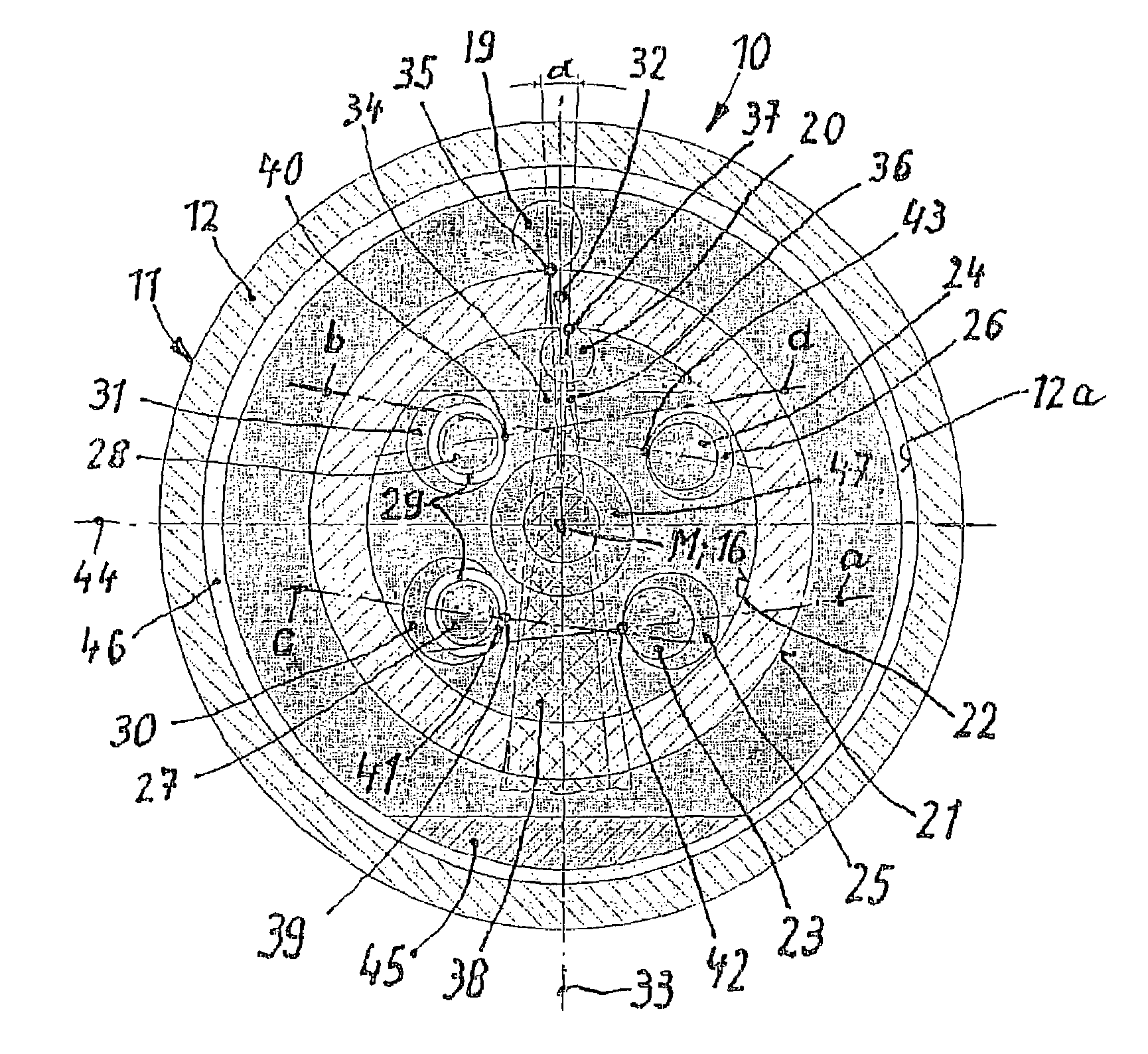
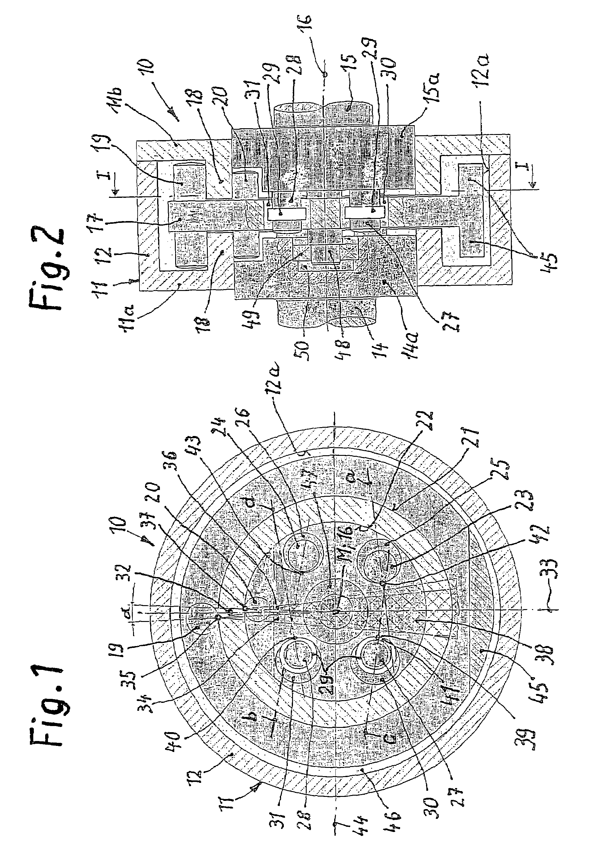
[0029]FIGS. 1 and 2 show a cross-section or longitudinal section of load torque lock 10 in accordance with the invention. It has a stationary housing 11 fixed to a frame with an external cylindrically embodied housing wall 12 and flange-like front sides 11a and 11b, on which a drive shaft 14 with a flange-like end 14a is pivoted on the one side 11a and an output shaft 15 with a flange-like end 15a is pivoted on the other side 11b. The drive shaft and output shaft 14, 15 lie on a common axis of rotation 16. Arranged between their spaced-apart, flange-like ends 14a, 15a is a locking body in the form of a locking disk 17 in a housing 11, which cooperates via locking means with locking rings fixed with the housing. The locking rings are embodied in the exemplary embodiment as a locking ring walls 18 projecting from the two front sides 11a, 11b of the housing 11 towards the inside until in front of the locking disk 17 and concentric to the axis of rotation 16. Serving as locking elements...


PUM


Abstract

The invention concerns a load torque lock for automatically locking load-side torques in the case of a decrease or cessation of a drive-side torque having a housing (11) fixed to a frame, a locking ring (17) permanently connected to it and a locking body (17) cooperating with it and revolving on the drive side, with locking devices which, on the one hand, clamp on the locking ring (17) with the occurrence of a load torque by swiveling the locking body (17) by means of locking elements (27, 28) of the output shaft (15) and, on the other hand, release from the locking ring (17) by swiveling the locking body (17) back by means of driving elements (23, 24) of the drive shaft (14). To avoid undesired friction or defective jamming of the locking devices on the locking ring (18) by the centrifugal forces of the locking body (17) it is embodied in such a way that its mass center of gravity (M) lies in the area of the rotational axis of the drive shaft and the output shaft that are aligned with one another.

Description

BACKGROUND OF THE INVENTION[0001]The invention concerns a load torque lock for automatically locking load-side torques.[0002]Load torque locks belong to the species of automatically locking locks and are used in terms of their functioning with self-switching free-wheel mechanisms. They are installed as locking elements in a drive train and automatically block the torques initiated by the output mechanism in one or both directions of rotation when the driving mechanism is at an standstill, while the torques initiated by the drive side are transmitted in the one or the other direction of rotation. As a result, torques acting on the load side in a drive train can be supported and locked with the aid of the load torque lock against a stationary frame or housing. It forms a safety element, which prevents impermissible movement of the load side from outside forces or torques in the case of a decrease or cessation of the driving mechanism. Such load torque locks are suited especially for u...

Claims


Application Information

Patent Timeline
Patent Type & Authority Patents(United States)
IPC IPC(8): F16D41/10F16D59/00
CPCF16D41/10
Inventor DREWE, INGOSCHNEIDER, GUIDO
Owner ROBERT BOSCH GMBH
Why Eureka
Try Eureka