Device for mixing fluids

a technology for mixing fluids and fluids, applied in flow mixers, indirect carbon-dioxide mitigation, image data processing details, etc., can solve the problems of marked reduction in the efficiency of the nozzle, failure of the function of the nozzle and the downstream fuel cell, etc., to achieve significant improvement in operating safety and reliability, and reduce efficiency

Inactive Publication Date: 2006-02-07
ROBERT BOSCH GMBH
View PDF11 Cites 25 Cited by
  • Summary
  • Abstract
  • Description
  • Claims
  • Application Information

AI Technical Summary

Benefits of technology

[0005]The device for mixing fluids of the invention has the advantage that a reduction in the efficiency, a failure in operation from condensation, stopping up or icing, for instance, is effectively suppressed, so that overall, operating safety and reliability are improved considerably compared to the prior art. Especially in the case of the device of the invention, it is assured that icing from condensation of water does not occur in its outlet region.
[0006]For instance, it is especially advantageous if the means for generating turbulence has a body, in particular a rod or an arrangement of rods, a ring or an arrangement of rings, a small plate, a perforated screen, a shower head, or a sieve, that is exposed to or introduced into the flow of the fluid, which in particular is disposed as immediately as possible upstream of the heater in such a way that as a result of the turbulence generated by way of it, an especially effective heat transfer from the heater into the fluid bathing the heater is achieved. Moreover in this way, the fluid delivered to the device of the invention is also heated more uniformly. It is especially advantageous in this respect if the heater is disposed directly downstream of the means for generating turbulence, and in particular is spaced apart parallel from it. Moreover, especially simple heating of the fluid is attained by using an electric heater, for instance with a heating wire, a heating ring, or a corresponding arrangement of wires or rings.
[0010]It is also advantageous if at least one of the fluid-carrying devices is provided superficially, in at least some regions, with a coating, in particular a Teflon coating, which counteracts adhesion, precipitation, or condensation of the applicable fluid carried in the fluid-carrying device, or of a fluid in contact with it on the outside of the fluid-carrying device.

Problems solved by technology

Often, the problem arises that the steam delivered condenses inside the nozzle or inside the nozzle valve, causing it to freeze and thus become plugged, or causing failure in the function of the nozzle and the downstream fuel cell, or a marked reduction in the efficiency of the nozzle.

Method used


Image

  • Device for mixing fluids
  • Device for mixing fluids
  • Device for mixing fluids

Examples


Embodiment Construction

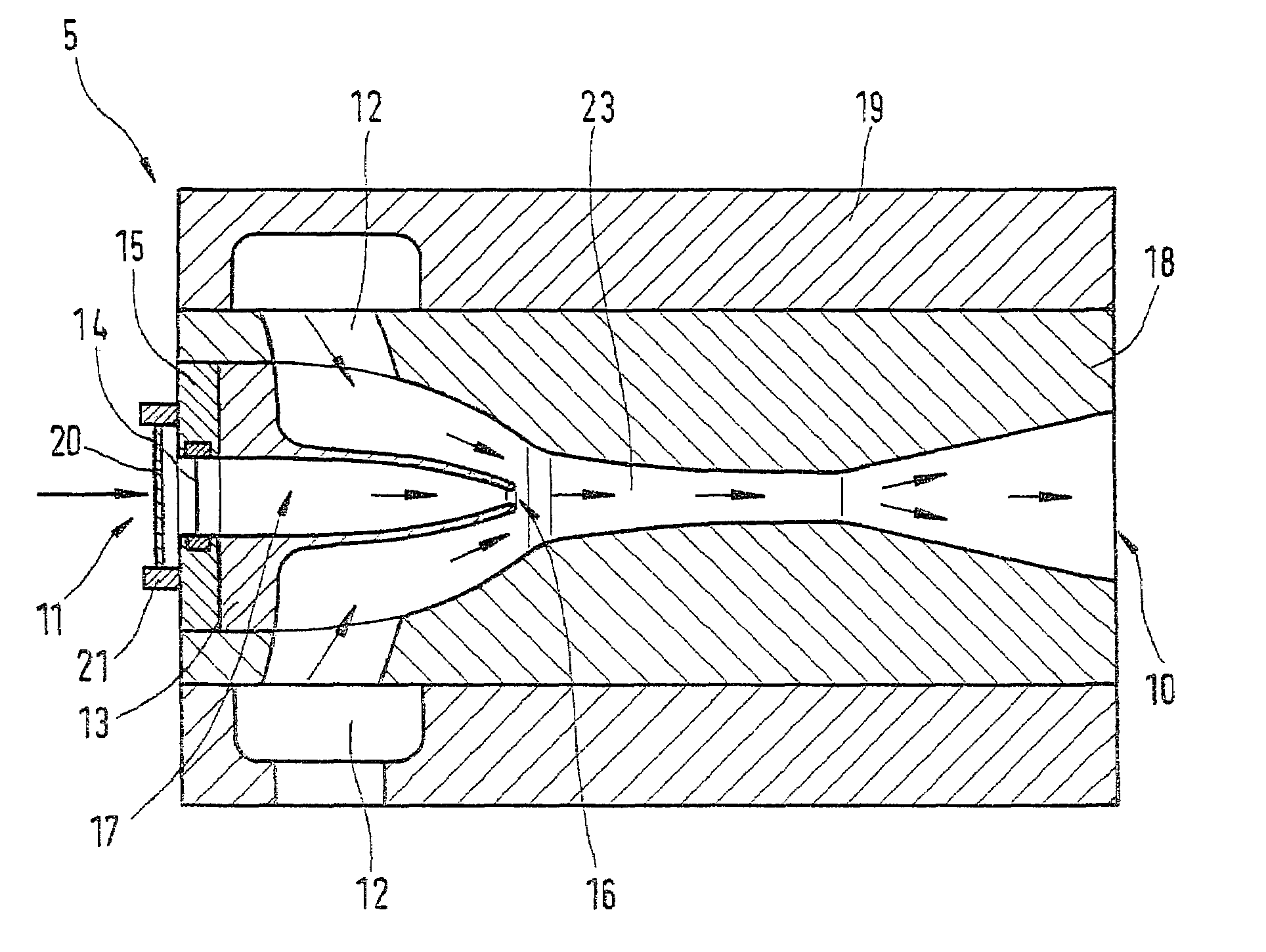
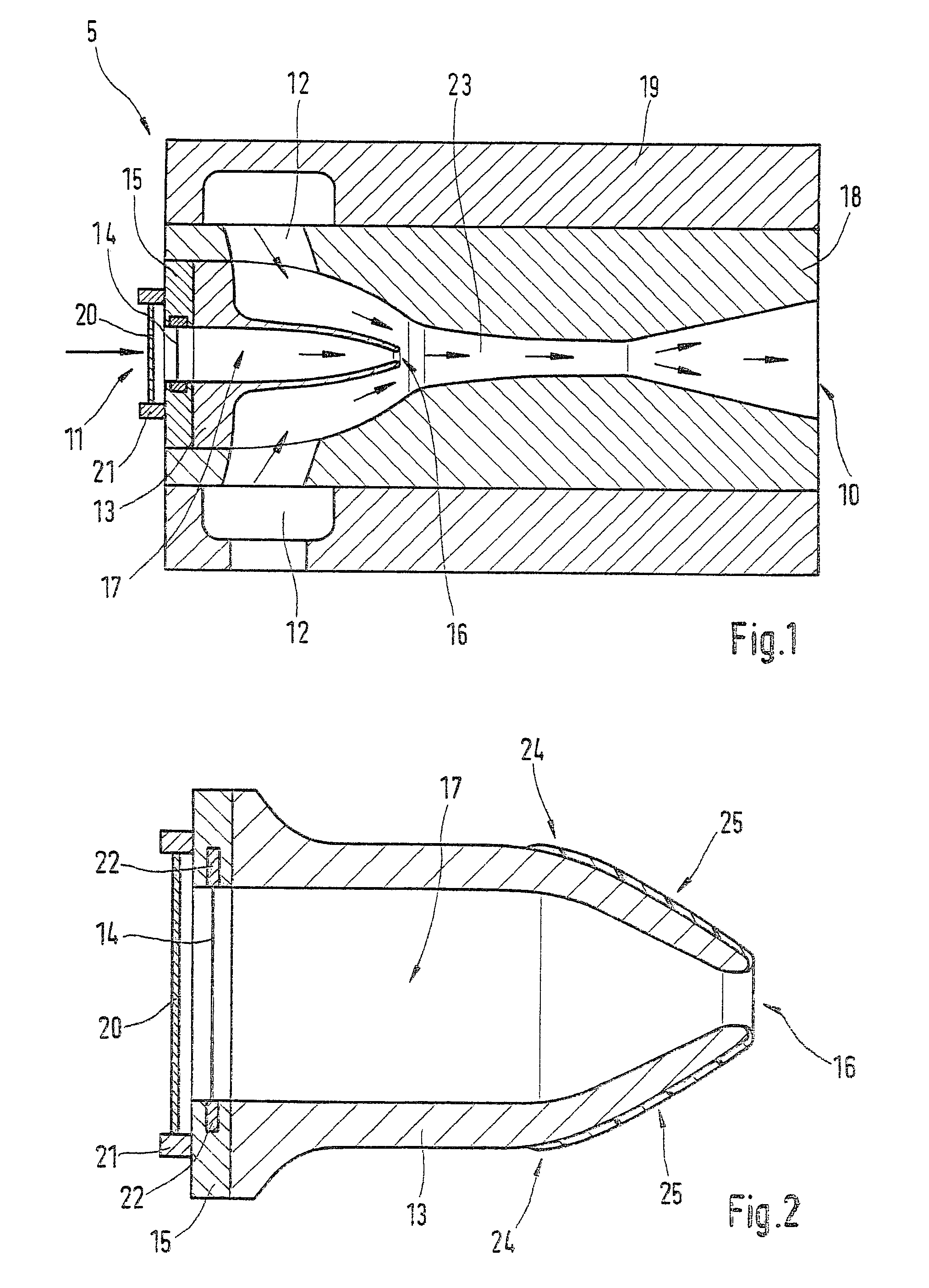
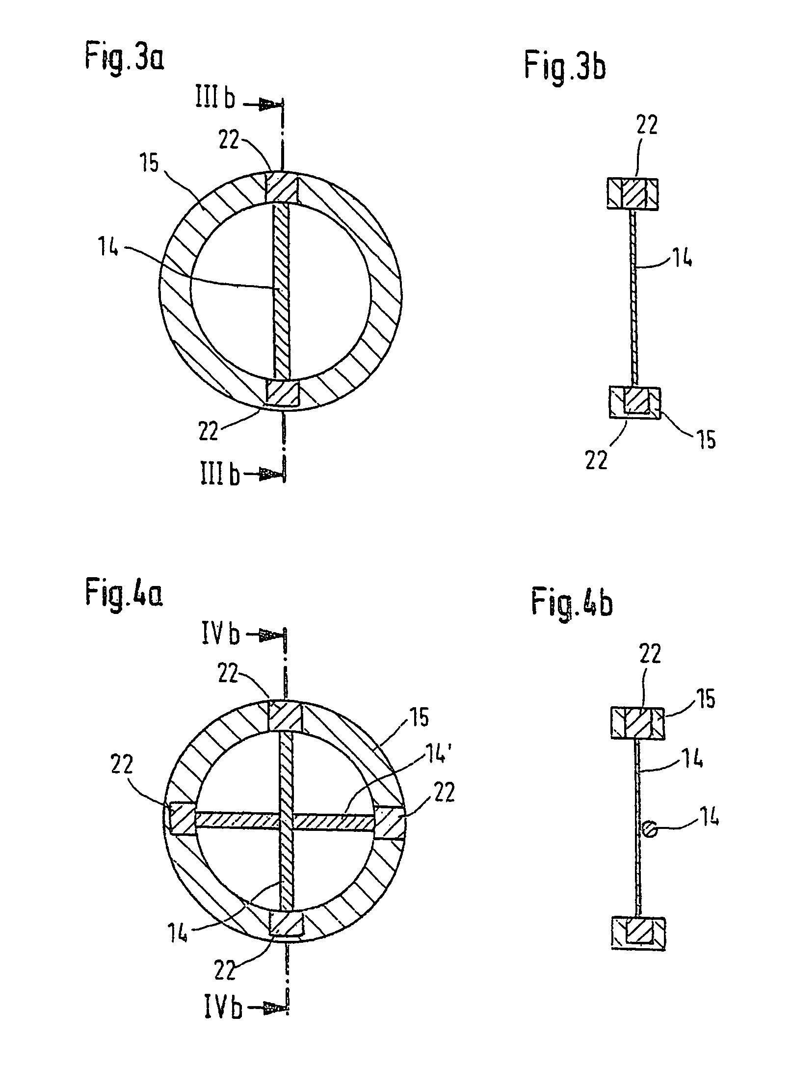
[0019]FIG. 1 shows a fluid mixing device 5, which is embodied as a gas injection valve or mixing nozzle. In particular, the fluid mixing device 5 is a jet compression nozzle, in which a strong propelling flow through the nozzle drags another, weaker flow along with it. For instance, in the fluid mixing device 5 described, hydrogen and saturated steam are mixed with one another in a mixing tube or mixing region inside the mixing device 5.

[0020]For that purpose, the fluid mixing device 5 has a base body 18, which is surrounded by a sleeve 19 with an annular conduit, by way of which a first fluid, such as hydrogen or a gas containing hydrogen, can be delivered to the base body 18. Also provided in the base body 18 is a funnel-shaped recess, which discharges into a central conduit 23 that leads to an outlet 15 of the fluid mixing device 5 that widens in funnel-like fashion. The sleeve 19 or base body 18 of FIG. 1 is preferably embodied cylindrically symmetrically.

[0021]FIG. 1 also shows...


PUM

PropertyMeasurementUnit
temperatureaaaaaaaaaa
areaaaaaaaaaaa
shapeaaaaaaaaaa

Abstract

A device for mixing fluids, in particular a gas injection valve, nozzle valve, mixing nozzle or jet compressor, is proposed. To that end, a first fluid-carrying device (12) for carrying a first fluid and a second fluid-carrying device (13) for carrying a second fluid are provided; the fluids are mixed with one another in a mixing region (16) that is in communication with the fluid-carrying devices (12, 13). In addition, a means (20) for generating turbulence in the applicable fluid and a heater, with which the fluid can be heated before reaching the mixing region (16), disposed downstream of the means (20) for generating turbulence in terms of the flow direction of the applicable fluid are associated with at least one of the fluid-carrying devices (12, 13). The proposed device is used in particular for mixing hydrogen and saturated steam and to deliver this mixture to a fuel cell.

Description

BACKGROUND OF THE INVENTION[0001]The invention relates to a device for mixing fluids, in particular a gas injection valve, mixing nozzle or jet compression nozzle, for instance for use to deliver fuel to a fuel cell, as generically defined by the preamble to the main claim.[0002]In the operation of fuel cells, it is known to supply them with a mixture of hydrogen and saturated steam; the mixture quantity of hydrogen and saturated steam, and its composition, are metered in or adjusted via a nozzle valve.[0003]Often, the problem arises that the steam delivered condenses inside the nozzle or inside the nozzle valve, causing it to freeze and thus become plugged, or causing failure in the function of the nozzle and the downstream fuel cell, or a marked reduction in the efficiency of the nozzle.[0004]The object of the present invention was to furnish a device for mixing fluids, in particular for mixing hydrogen and in particular saturated steam, that can also be used to deliver fuel to a ...

Claims


Application Information

Patent Timeline
Patent Type & Authority Patents(United States)
IPC IPC(8): F23D11/10B65B57/02B01F23/10B65B57/18B67B1/00B67B3/26F23D11/40F23D11/44F23D14/64F23D14/66F23M5/02G06T1/00H01M8/04007H01M8/04089H01M8/04119
CPCB01F5/0413B01F5/0473B01F15/066F23D11/402F23D11/44F23D14/64F23D14/66F23M5/025H01M8/04007H01M8/04089B01F5/0428Y02E60/50B01F2005/0025B01F2005/0048B01F2015/062H01M8/04119Y02E20/34B01F2025/916B01F2025/919121B01F25/31242B01F25/3141B01F25/312B01F35/93B01F2035/99
Inventor FAYE, IANNGUYEN-SCHAEFER, THANH-HUNG
Owner ROBERT BOSCH GMBH
Why Eureka
Try Eureka