In-tube solenoid gas valve

Active Publication Date: 2006-02-07
WANG WEI CHING +1
View PDF4 Cites 58 Cited by
  • Summary
  • Abstract
  • Description
  • Claims
  • Application Information

AI Technical Summary

Benefits of technology

[0012]Hence, in the current design, described hereafter, the stroke of the movement of magnetic rod is not affected by the required stroke of that of the solenoid assembly. The stroke of the magnetic rod is minimized and the stroke of the solenoid assembly is maximized to result in a reduction of the electri

Problems solved by technology

The configuration of piping systems is complex in alternative fuel vehicles.
Because of the inlet pressure restrictions and temperature variations, it is difficult to design an appropriate valve that meets all the r

Method used


Image

  • In-tube solenoid gas valve
  • In-tube solenoid gas valve
  • In-tube solenoid gas valve

Examples


Embodiment Construction

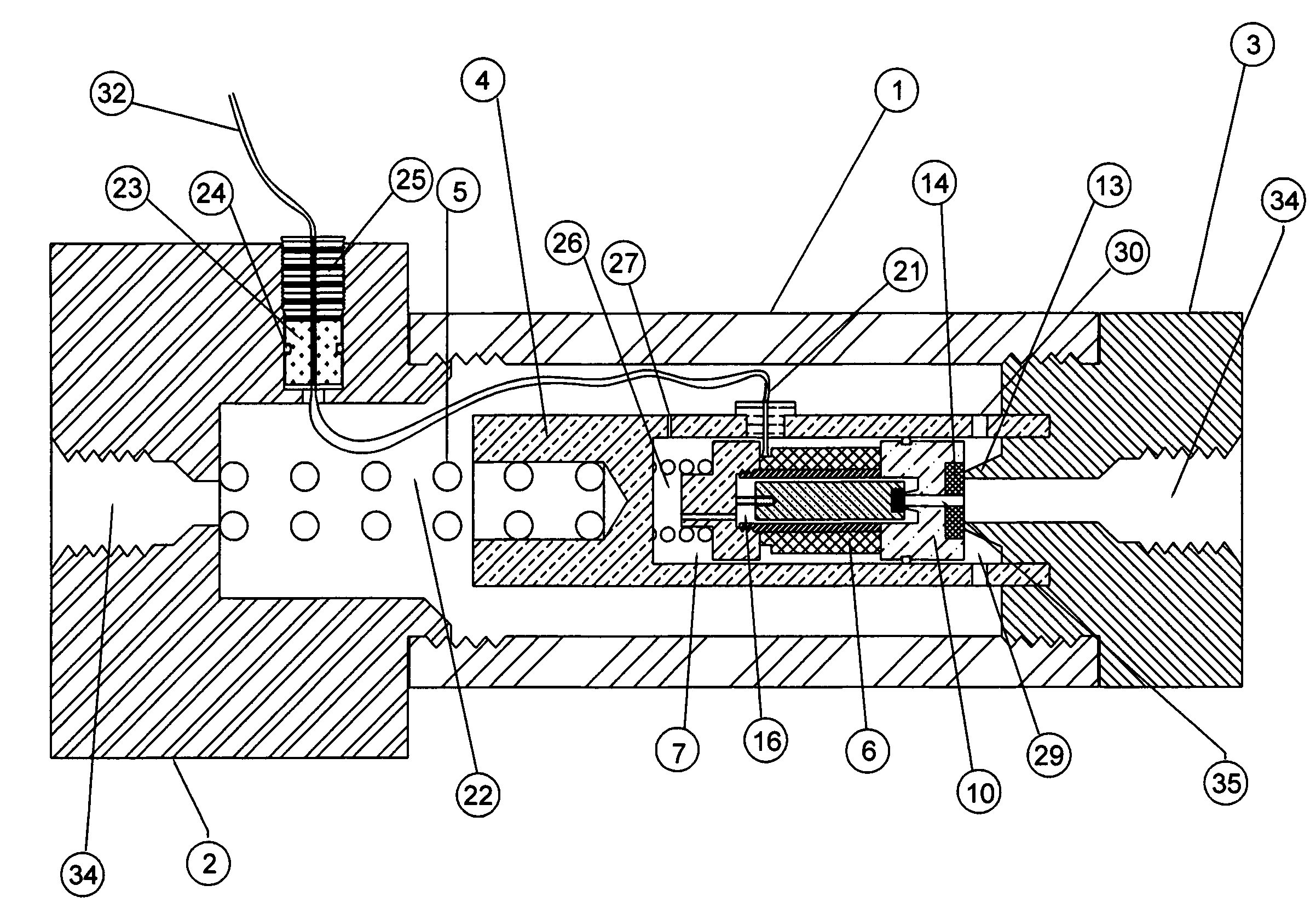
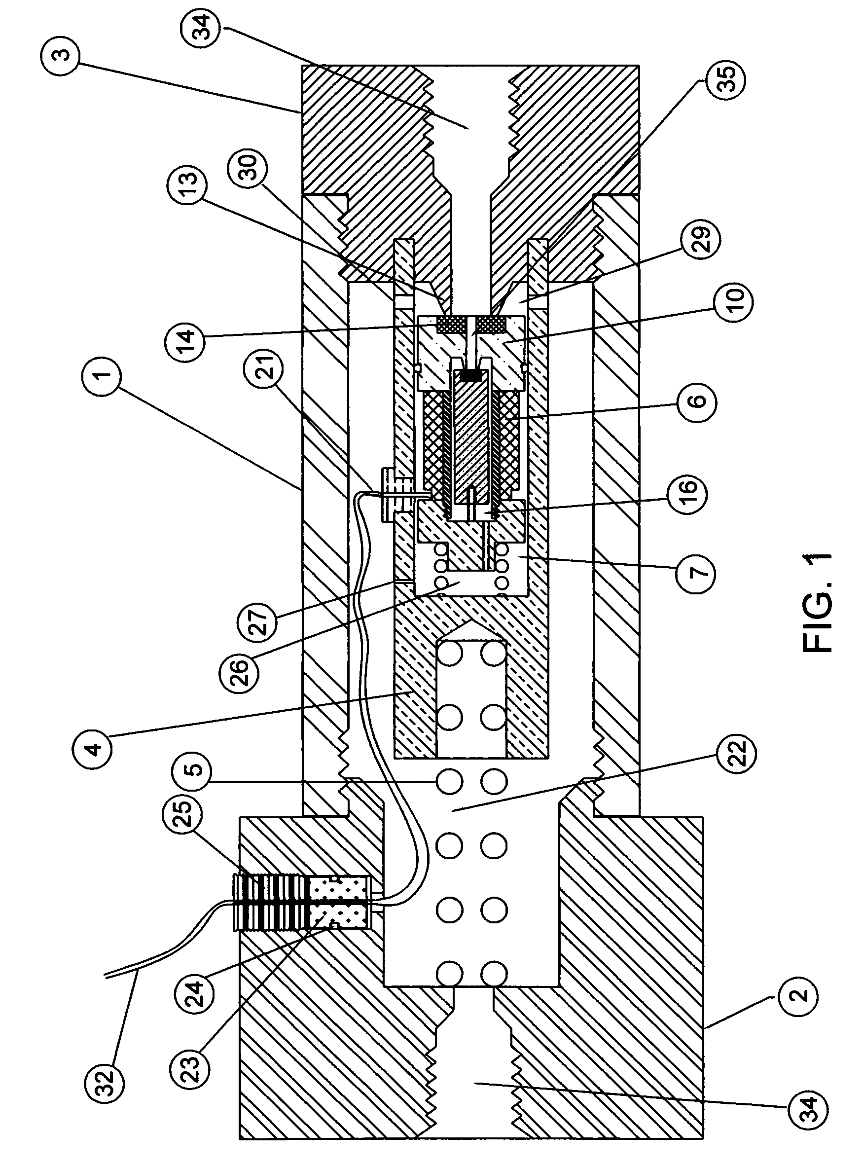
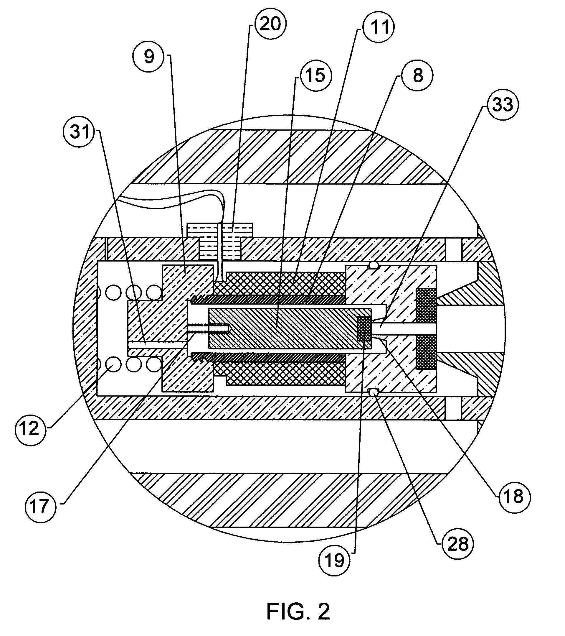
[0021]Attention is first directed to FIG. 1 and FIG. 2, which shows an in-tube solenoid gas valve in section view. The valve tube 1 has a hollow hole with internal threads at both ends, to accept both inlet fitting 2 and outlet fitting 3. Both fittings have an axial hole 34 with internal threads for connecting adaptive fittings of piping system. A support cylindrical body 4, pushed by a compression spring 5 against said outlet fitting 3, having a chamber 7, provides the space for movements of the solenoid assembly 6 which comprises of a hollow sleeve 8, a stop 9, a flange 10 and an electrical coil 11.

[0022]A compression spring 12 pushes said solenoid assembly 6 to the seal seat 13 of said outlet fitting 3 at “closed” state. A plastic insert 14 is molded onto said flange 10 to provide seal. A magnetic rod 15 moveable axially in the hollow space 16 of said solenoid assembly 6, while a compression spring 17 pushes said magnetic rod 15 against the small seal seat 18 of said flange 10 at...


PUM


Abstract

A solenoid gas valve having a solenoid assembly and inlet and outlet fittings is installed inside a tube. The opening and closing of the valve is operated by the pressure difference with an aid of the magnetic field. A compression spring is attached to the support cylindrical body and held against the inlet end fitting while a moving solenoid assembly is located inside the support cylindrical body. The moving solenoid assembly that consists of a stop, a flange, a sleeve and an electrical coil, is held by a second compression spring that is attached to the inside of the support cylindrical body. A small moving magnetic rod, slides inside the sleeve of the solenoid assembly. Acted by a third compression spring, the magnetic rod seals the gas outlet through the bleed orifice on the flange of the solenoid assembly.

Description

BACKGROUND OF THE INVENTION[0001]The configuration of piping systems is complex in alternative fuel vehicles. The fuel, either natural gas or hydrogen, is normally stored in a high pressure tank, controlled by solenoid gas valves when it is in operation. Generally, the space in a vehicle is limited; hence a small size of valves and piping systems is desired. In addition, having an in-line inlet and outlet ports would simplify the arrangement of piping systems.[0002]Valves are used to control the flow rate of the fuel under a specified inlet pressure. Because of the inlet pressure restrictions and temperature variations, it is difficult to design an appropriate valve that meets all the requirements for the piping systems. Solenoids of a reasonable size can typically produce a pulling force that is approximately only 1 / 100 of the force necessary to unseat a valve that is being forced shut by the high-pressure gases. To overcome this, most of the gas valves adopt a two-stage process in...

Claims


Application Information

Patent Timeline
IPC IPC(8): F16K31/02
CPCF16K31/408F16K1/12
Inventor WANG, WEI-CHINGWANG, CHIA-PING
Owner WANG WEI CHING
Why Eureka
Try Eureka