Self-attaching nut
a self-attaching and nut technology, applied in the direction of threaded fasteners, screwdrivers, manufacturing tools, etc., can solve the problems of thread cylinder deformation or distortion, and achieve the effect of improving push-off strength and torque resistance, improving torque resistance, and improving torque resistan
- Summary
- Abstract
- Description
- Claims
- Application Information
AI Technical Summary
Benefits of technology
Problems solved by technology
Method used
Image
Examples
first embodiment
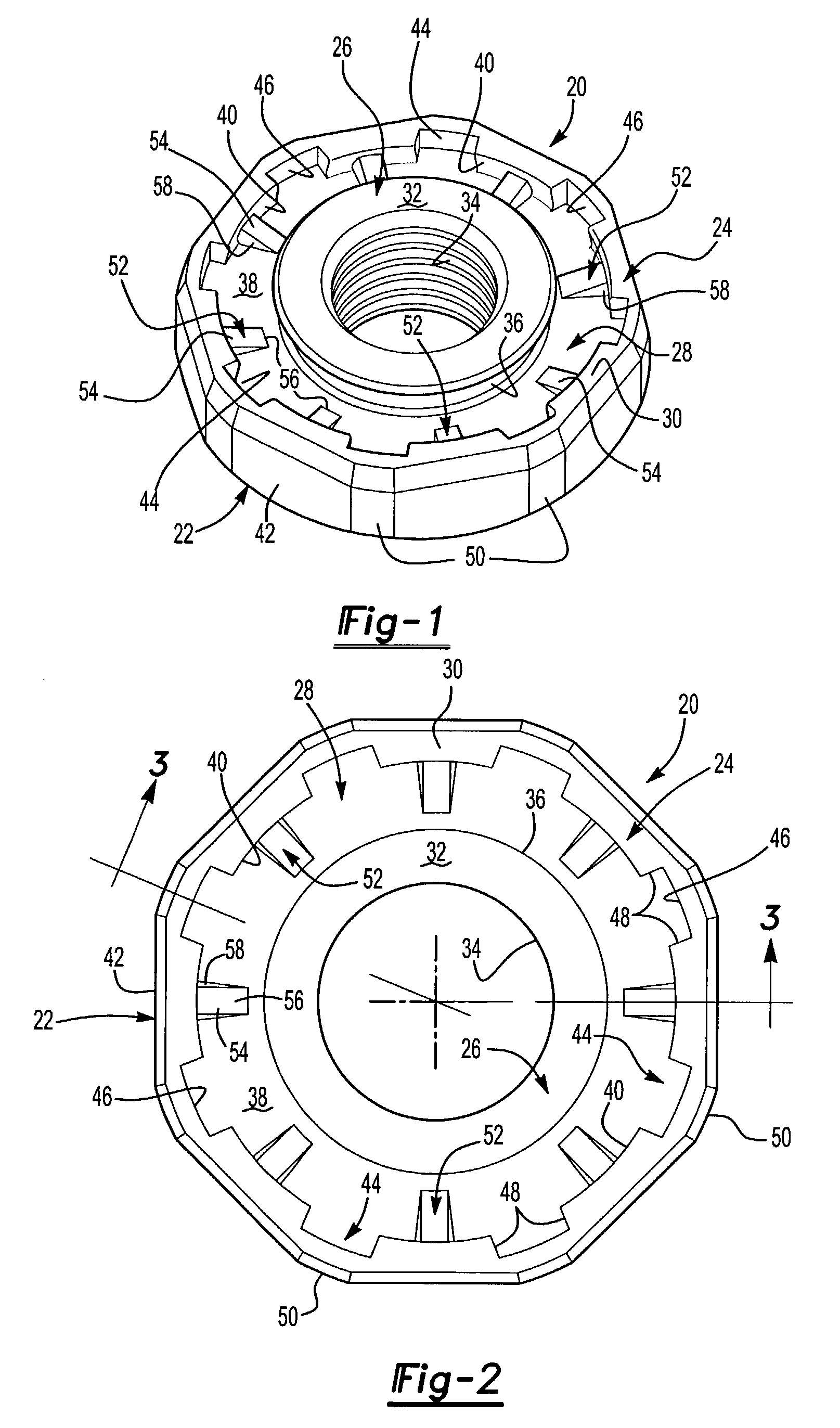
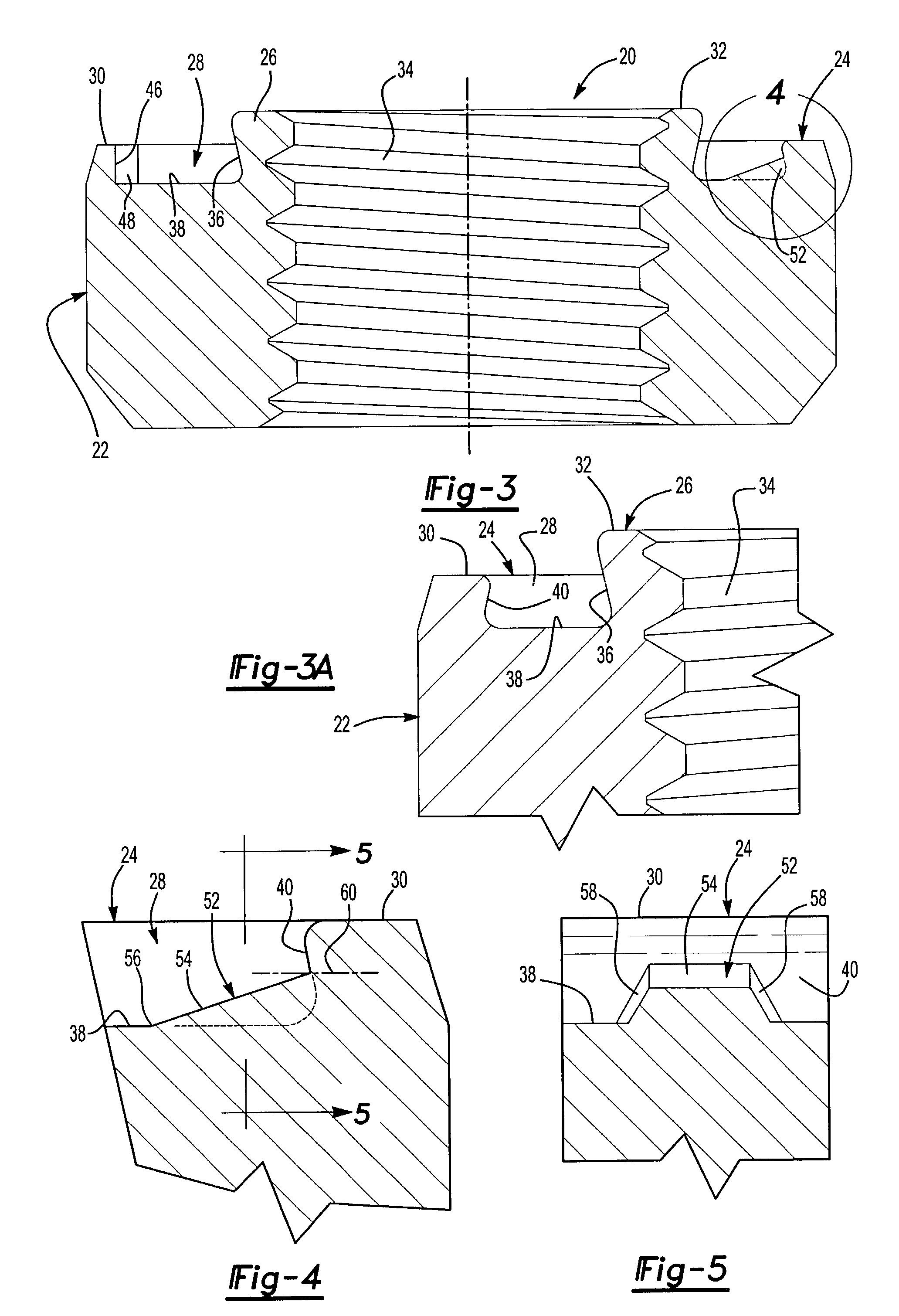
[0042]As will be understood, the following description of the preferred embodiments and the appended drawings are for illustration purposes only and do not limit the scope of this invention except as set forth in the following claims. FIGS. 1 to 5 illustrate the self-attaching nut 20 of this invention including a body portion 22 having an end face 24 (see FIG. 1), a central pilot portion 26, an annular groove 28 surrounding the pilot portion 26 and an annular panel support face 30 surrounding the annular groove 28. The pilot portion 26 includes an annular preferably planar end face 32 and a bore 34 through the pilot portion. Where the self-attaching nut 20 of this invention is utilized as a pierce nut, the end face 32 is preferably above the plane of the annular panel support face 30, as best shown in FIG. 3, such that the pilot portion 26 pierces an opening in a metal panel as is well known in this art. As best shown in FIG. 3A, the annular groove 28 includes an inner side wall 36 ...
second embodiment
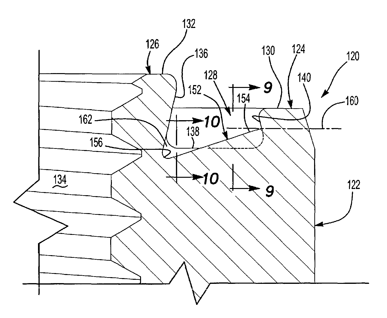
[0046]FIGS. 6 to 10 illustrate a self-attaching nut 120 of this invention, wherein the common elements of the self-attaching nut 120 are numbered the same as the elements of the self-attaching nut 20 described above except that the elements of the self-attaching nut 120 are numbered in the 100 series to simplify the description of the self-attaching nut 120. That is, the self-attaching nut 120 shown in FIGS. 5 to 10 include a body portion 122 having an end face 124, a central pilot portion 126, an annular groove 128 surrounding the pilot portion and an annular panel support face 130 surrounding the annular groove 128. In this embodiment of the self-attaching nut 120, the radial ribs 152 are integral with the inclined outer side wall 140, generally equally spaced between the radial notches 144, as described above in regard to the self-attaching nut 20 shown in FIGS. 1 to 5. However, the top face 154 of the radial ribs extends below the plane of the bottom wall 138 of the annular groo...
fourth embodiment
[0050]the self-attaching nut 320 shown in FIGS. 16 and 17 differs from the embodiment of the self-attaching nut 20 shown in FIGS. 1 to 5 in two material respects. First, the bottom wall 338 of the annular groove 328 includes a plurality of alternating circumferentially spaced ribs 352 and 353, including a first plurality of circumferentially spaced radial ribs 352 integral with the outer side wall of the annular groove 328 and a second plurality of radial ribs 353 integral with the inner side wall 336 of the annular groove 328. In a preferred embodiment of the self-attaching nut 320, the radial ends 356 of the radial ribs 352 and 353 extend beyond a midportion 364 of the annular groove 328, such that the alternating radial ribs 352 and 353 circumferentially “overlap.” That is, the radial inner ends 356 of the radial ribs 352 extend beyond the radial inner ends 356 of the radial ribs 353 in the bottom wall 338 of the annular groove 328, such that the radial ribs 352 and 353 circumfer...
PUM
| Property | Measurement | Unit |
|---|---|---|
| resistance | aaaaa | aaaaa |
| push-off strength | aaaaa | aaaaa |
| torque resistance | aaaaa | aaaaa |
Abstract
Description
Claims
Application Information
 - R&D
- Intellectual Property
- Life Sciences
- Materials
- Tech Scout
- Unparalleled Data Quality
- Higher Quality Content
- 60% Fewer Hallucinations
Browse by: Latest US Patents, China's latest patents, Technical Efficacy Thesaurus, Application Domain, Technology Topic, Popular Technical Reports.
© 2025 PatSnap. All rights reserved.Legal|Privacy policy|Modern Slavery Act Transparency Statement|Sitemap|About US| Contact US: help@patsnap.com


