Method and apparatus for electrostatic dispensing of microdroplets

a technology of electrostatic dispensing and microdroplets, which is applied in the field of electrostatic dispensing of microdroplets, can solve the problems of inability to quickly produce very dense arrays, and inability to dispense femtoliter volumes of samples, etc., and achieves the effect of reducing the number of microdroplets

Inactive Publication Date: 2006-02-07
SRI INTERNATIONAL
View PDF46 Cites 57 Cited by
  • Summary
  • Abstract
  • Description
  • Claims
  • Application Information

AI Technical Summary

Problems solved by technology

This is especially true in situations involving expensive substances.
Generally, these devices are unsuitable for quickly producing very dense arrays, since only a few microdroplets (usually 8 or 12) can be laid down at a time with such devices.
Furthermore, these micropipette devices are typically not capable of dispensing femtoliter volumes of samples.
Thus, the production of very dense arrays, e.g., having hundreds or thousands of microdroplets tends to be a very tedious and time-consuming process.

Method used


Image

  • Method and apparatus for electrostatic dispensing of microdroplets
  • Method and apparatus for electrostatic dispensing of microdroplets
  • Method and apparatus for electrostatic dispensing of microdroplets

Examples


example 1

[0057]Table 1 below shows data obtained from experiments performed in support of the present invention. As can be seen from the data, a controlled and defined fluid drop volume may be transferred when various parameters are adjusted. The parameters include the pulse voltage, pulse width / frequency, distance of the second electrode from the meniscus, and fluid composition. When referring to pulse width / frequency in the table, “triangle” means that the voltage was increased from the steady voltage to the sum of the steady and pulse voltages, and when the maximum voltage was measured, the voltage was immediately reduced to the steady voltage. Fluid A is DMSO; fluid B is 0.1% Triton X-100 in 100% DMSO; fluid C is 30% DMSO in 50 mM HEPES; fluid D is 0.1% Triton X-100 in 30% DMSO; and fluid E is 15% DMSO in 50 mM HEPES.

[0058]

TABLESteady VoltagePulse VoltageDistanceDrop Volume(kV)(kV)Pulse Width / Frequency(mm)(nl)FluidMaximum Voltage1.512 s1688 ± 18 Asteady voltage + pulse voltage1.514 s1107...


PUM

PropertyMeasurementUnit
voltageaaaaaaaaaa
voltage potentialaaaaaaaaaa

Abstract

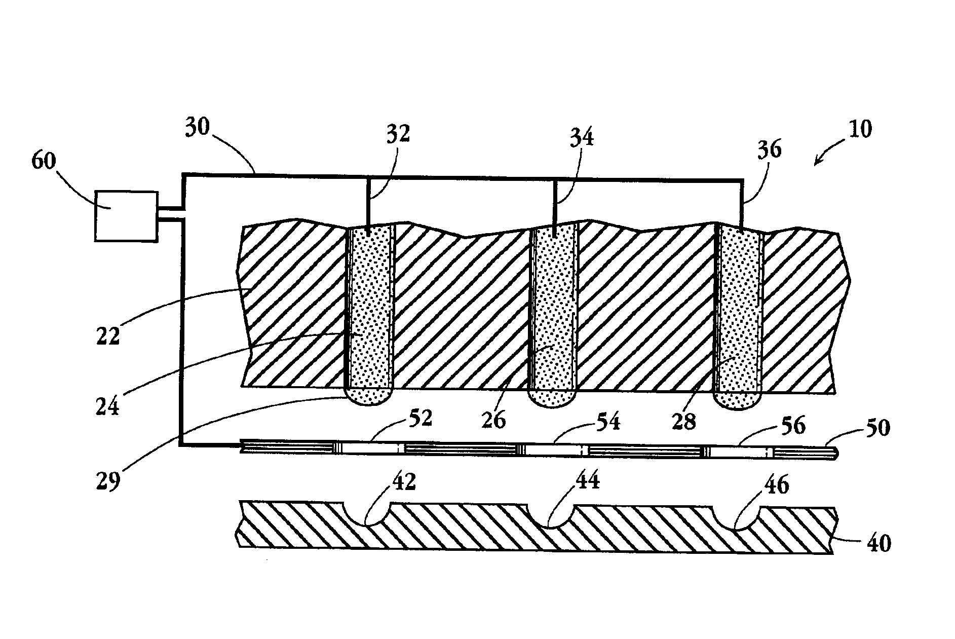
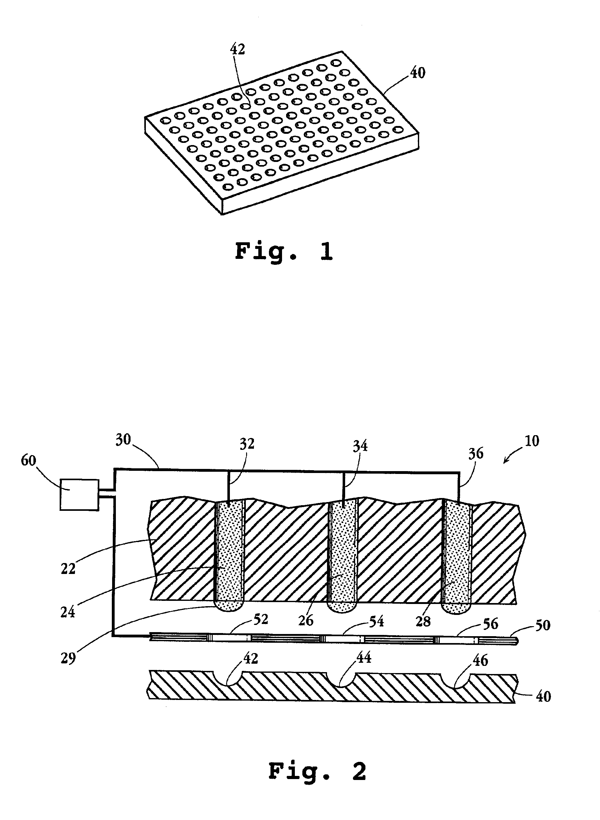
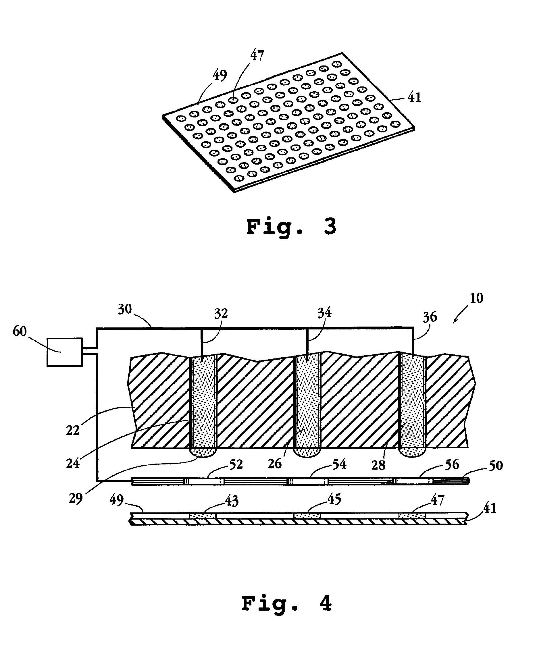
An apparatus and device for dispensing femtoliter to nanoliter volumes of liquid samples are disclosed. The apparatus includes a liquid-support plate, two electrodes, a substrate, and a control unit. The liquid support plate has a plurality of liquid-support regions, each capable of supporting a liquid meniscus thereon. The first electrode contains a plurality of electrode connections, each operatively connected to one of the liquid support regions, for electrical contact with a meniscus supported in such region. The substrate has a first side confronting the plate and an opposite side, and a plurality of sample-holding regions formed in the first side. The second electrode is disposed adjacent one of the two substrate sides. Thus, a selected volume of the liquid can be ejected from or to one or more of the liquid-support regions to or from one or more of the sample-holding regions.

Description

FIELD OF THE INVENTION[0001]The present invention relates to an apparatus for loading and dispensing small volumes of liquid samples electrostatically, and to methods employing the apparatus.BACKGROUND OF THE INVENTION[0002]As the sensitivity of analytical techniques continues to improve, it is increasingly desirable to carry out chemical and biochemical reactions and / or analyses using very small volumes of samples and reagents. This is especially true in situations involving expensive substances. Accordingly, it is now popular to utilize very small volumes of such substances laid down as microdroplets on the surface of, or inside, a well or substrate, such as a slide, micro-card, chip or membrane.[0003]Not only is it often desirable to transfer ultra-small volumes of individual samples and reagents in the form of droplets, it is becoming increasingly popular to arrange numerous such microdroplets in close proximity to one another in the form of an array on a substrate. High-density...

Claims


Application Information

Patent Timeline
Patent Type & Authority Patents(United States)
IPC IPC(8): G01N1/10B67D5/22B67D5/08B01L3/02B01L3/00B67D7/08B67D7/22
CPCB01L3/0244B01L3/0268B01L3/5085B01L2300/0819Y10T436/2575B01L2300/161B01L2400/027B01J2219/00274B01L3/021B01L2300/0838
Inventor SMITH, CHRIS D.GARCIA, PABLO E.LOW, THOMAS P.SHRADER, ERIC J.
Owner SRI INTERNATIONAL
Why Eureka
Try Eureka