Device for bioassay and methods for preparation and use thereof

a bioassay and device technology, applied in the field of bioassays, can solve the problems of increasing the risk of antimicrobial resistance significantly, affecting the accuracy of the results, and the complexity of the process, so as to achieve the effect of minimal hands-on time, sensitivity and ease of us

Pending Publication Date: 2020-10-22
UTILIZER AB
View PDF0 Cites 0 Cited by
  • Summary
  • Abstract
  • Description
  • Claims
  • Application Information

AI Technical Summary

Benefits of technology

[0015]The present disclosure manages to bring the sensitivity and ease-of-use of previously known digital assays to a point-of-care format. In one preferred embodiment, a “dip-and-swipe” action can be used during the operation of the device, which “dip-and-swipe” action requires no technical skills from the end-user and requires a minimal hands-on-time. Further, in a preferred embodiment, the device operation does not require equipment for fluid actuation. In one preferred embodiment, readout of the device can be accomplished by the naked eye. In another preferred embodiment, readout of the device can be accomplished by a cell phone camera.

Problems solved by technology

Unnecessary antibiotic treatment of UTI increases the risk of developing antimicrobial resistance significantly.
However, the rapid, uncomplicated, low cost and automated addition of detection reagents to the samples after digitization remains an unresolved challenge.
However, this format constitutes a rather bulky linear comb-like array of many tubes in which each capillary provides a non-digital readout, and which format prevents extending the approach towards the degree of digitisation needed in bioassays.
However, the method has not been shown for detection of bacteria without extensive off-chip sample preparation.
Even though recently published slipchip-based antibiotic susceptibility tests (AST) provide very rapid results, the current approach is unable to give AST results for bacterial concentrations below 105 CFU / ml [13].
However, the format still requires bulky hardware to operate, which limits the PoC applications.
The present disclosure addresses three specific hurdles in infectious disease diagnostics:Digital bioassays are powerful tools for the quantification of biomarkers, but typically require complicated lab instruments for the digitisation of the sample and the readout.Hands-on time and the requirement of trained personnel limit the uptake of the new technologies in the medical setting.Low resource settings require diagnostic formats that do not rely on complicated external equipment.

Method used


Image

  • Device for bioassay and methods for preparation and use thereof
  • Device for bioassay and methods for preparation and use thereof
  • Device for bioassay and methods for preparation and use thereof

Examples


example 1

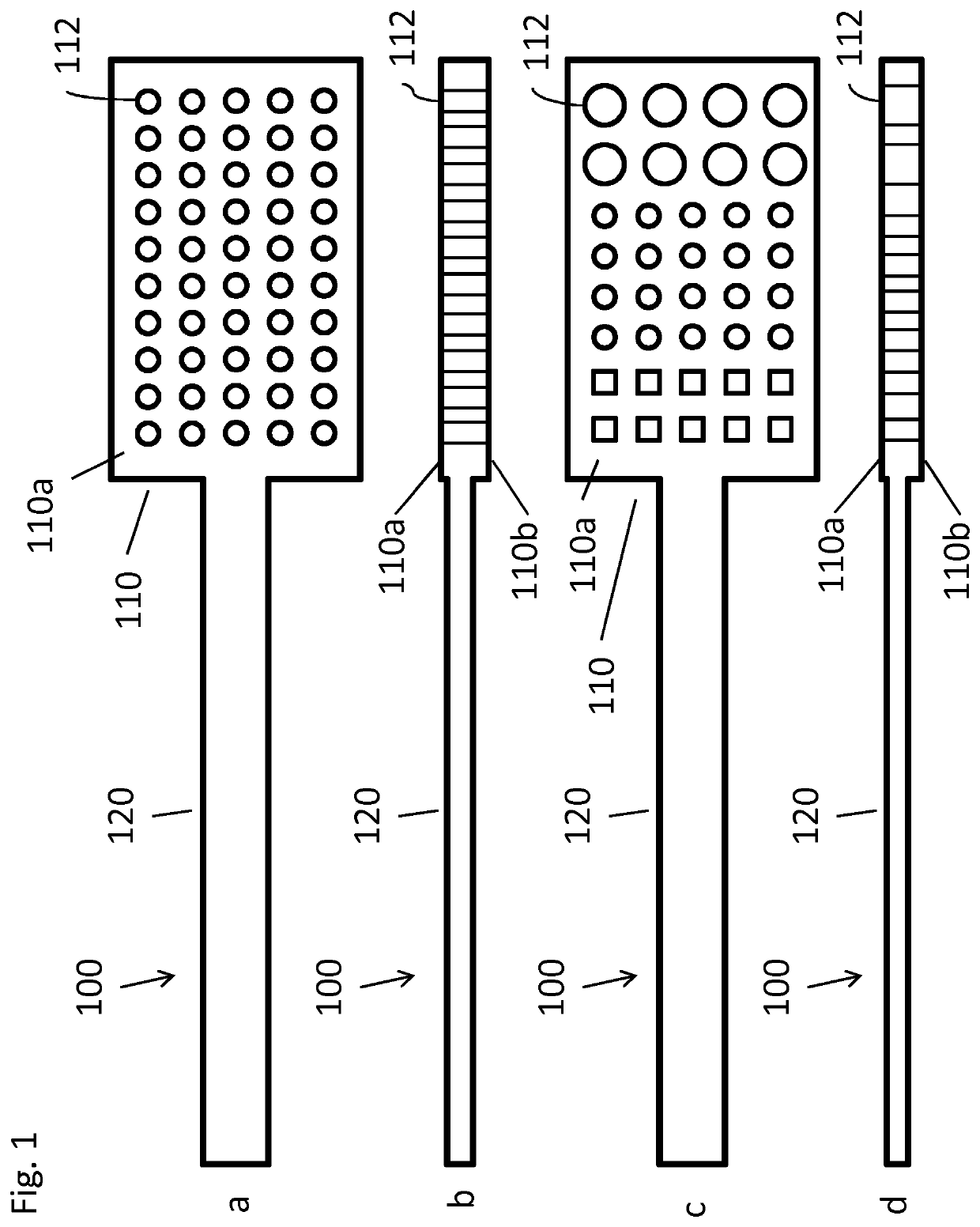
[0117]Our novel device consists of a dipstick in which an array of small through holes with well-defined volumes is created by laser drilling or molding. For example, a polymethyl methacrylate (PMMA) dipstick with an array of 180 holes of 200 nl volume fabricated by CO2 laser drilling.

[0118]The dipsticks are prepared in two steps:[0119]i) The device is dipped in gel solution such that the holes are filled. After filling, in-situ gelation of hydrogel occurs.[0120]ii) The device is washed and dried, resulting in a dried gel structure in each individual hole.

[0121]Operation of the dipstick requires three very simple and short steps:[0122]i) The dipstick is placed in bacterial sample for 1 minute, during which the dipstick holes are filled with sample (FIG. 2). Thereafter, the dipstick is swiped with a tissue to remove excess sample on the top and the bottom surface of the dipstick, but in which the gel retains the sample inside the holes.[0123]ii) The dipstick is placed on a chromogeni...

example 2

[0126]Dipstick preparation: Our novel device consists of a dipstick, in which we create (by drilling or molding) an array of small through-holes with well-defined volume. We fabricated dipstick hole arrays of 180 holes with volume 800 nL. The holes are filled with a hydrogel / toluene emulsion, after which the hydrogel is cross-linked, the toluene is replaced by IPA, the IPA is evaporated, and the gel is dried, resulting in a microporous dry gel structure in each of the holes.

[0127]Dipstick operation in four simple and short steps: The dipstick is i) placed in the bacterial sample for 1 minute, during which the dipstick holes fill with sample. ii) The dipstick is swiped dry on a tissue to remove the excess sample on the top and bottom surface of the dipstick, but in which the sample inside the holes is retained by the gel. The gel retaining the sample during swiping is the main “microfluidic” innovation. iii) Thereafter the stick is placed on a chromogenic agar (Chromagar Orientation,...

example 3

[0129]Our novel device consists of a dipstick in which an array of small through holes (capture zones) with well-defined volumes is created by laser drilling or molding. For example, a polymethyl methacrylate (PMMA) dipstick with an array of 180 holes of 200 nl volume fabricated by CO2 laser drilling.

[0130]The dipsticks are prepared in three steps:[0131]i) The device is filled with chromogenic agar (Chromagar Orientation, Chromagar, France) at 50° C., at which temperature the chromogenic agar is in liquid form.[0132]ii) After filling, device is cooled down to room temperature to form a gel in each hole.[0133]iii) The device is freeze dried, resulting in a microporous dried gel structure which contains bioassay reagents in each individual hole.

[0134]Operation of the dipstick requires three very simple and short steps:[0135]i) The dipstick is placed in bacterial sample (E. coli in broth) for 1 minute, during which the dipstick holes are filled with sample. Thereafter, the dipstick is ...


PUM

PropertyMeasurementUnit
distanceaaaaaaaaaa
depthaaaaaaaaaa
volumeaaaaaaaaaa

Abstract

The present disclosure is directed to a device (100) comprising a sampling part (110), wherein the sampling part (110) comprises an array of capture zones (112) for sampling liquid volumes between tens of microliters and femtoliters, wherein some or all of the capture zones (112) contain a sponge-like material. Also disclosed are a method for the preparation of such a device and a method for the detection and determination of the presence, concentration and/or properties of an analyte by contacting a liquid sample with such a device.

Description

FIELD OF THE DISCLOSURE[0001]The present disclosure relates to the field of bioassays. More particularly, the present disclosure is directed to devices and methods for performing a bioassay, such as a digital bioassay, for digitization of liquid samples for statistical analysis, for diagnostics testing or for detection and determination of concentration of chemical or biological substances, e.g. bio-reagents or pathogens.BACKGROUND OF THE DISCLOSURE[0002]The World Health Organization (WHO) identifies antimicrobial resistance (AMR) as one of the biggest threats to modern healthcare. The rapidly increasing antibiotic resistance problem affects all parts of the world and global solutions to solve this problem are urgently needed [1]. According to the final report of UK government Review on Antimicrobial Resistance, promoting new and rapid diagnostics to cut unnecessary use of antibiotics forms a crucial step to solve this problem [2].[0003]Urinary tract infections (UTIs) are one of the...

Claims


Application Information

Patent Timeline
Patent Type & Authority Applications(United States)
IPC IPC(8): B01L3/00B01J19/00G01N1/02
CPCB01L2300/161G01N1/02B01J2219/00619G01N2001/028B01J19/0046B01J2219/00644B01J2219/00286B01L3/508B01J2219/00317B01L2300/069B01L3/50857
Inventor ISERI, EMREVAN DER WIJNGAART, WOUTER
Owner UTILIZER AB
Why Eureka
Try Eureka