Pointing device with biometric sensor

a biometric sensor and pointing device technology, applied in the field of pointing devices, can solve the problems of limiting access to adult activities, affecting the accuracy of pointing devices, etc., and achieves the effect of convenient use, immediate implementation, and easy us

Inactive Publication Date: 2005-09-20
DALTON PATRICK ENTERPRISES
View PDF14 Cites 23 Cited by
  • Summary
  • Abstract
  • Description
  • Claims
  • Application Information

AI Technical Summary

Benefits of technology

[0016]The present invention includes a pointing device which incorporates a biometric sensor at a location such that when operating the pointing device in a normal manner, a user's hand rests naturally in a position to place a finger of the user's hand in proximity to and readable by the biometric sensor. The location of the biometric sensor is equally well suitable for use by either a right-handed or a left-handed user, irrespective of hand size. Along with positional information from a position sensor and user selection information from at least one user-depressable button, the pointing device of the present invention also conveys to an attached system information associated with the user's identity detected by the biometric sensor. In one embodiment, the biometric sensor is a fingerprint sensor. Such a pointing device is well suited to both transparent verification as well as continuous, real-time verification, for if a user removes his or her hand from the natural position when using the device, the user's fingerprint will no longer be detectable by the fingerprint sensor, and the attached electronic system can be alerted as to the need to re-authenticate any additional attempts at using the pointing device. Minimal technical knowledge is required for the identification functions are incorporated into a familiar pointing device. It affords a virtually foolproof, easily-used, and immediate method of identifying a user desiring access. A system audit log which records all attempted transactions, both authorized as well as non-authorized, may be easily implemented.

Problems solved by technology

These include limiting access to bank accounts, limiting access to certain facilities such as a security area, a computer room, a police department, or a military facility, limiting which people are authorized to pick up a child from a day care center, limiting access to government welfare checks and health benefits, determining which prisoner to parole, and limiting access to adult activities such as electronic gambling.
Biometric identification has gained interest in recent years because certain personal characteristics have been found to be substantially unique to each person and difficult to reproduce by an impostor.
Further, the recording and analysis of biometric data is generally susceptible to automation owing to the increased use of computer controlled electronics and digital recording techniques.
Hand or palm print techniques typically evaluate the shape of a person's hand or other significant features such as creases in the palm, but these techniques may be fooled by templates or models of the hand of an authorized person.
A drawback of this technique is that the blood vessel pattern may vary over time, e.g., when alcohol is in the blood stream or during irregular use of glasses or contact lenses.
Also, a user may feel uneasy about having his or her eye illuminated for retina scanning or the possibility of eye contamination if there is contact between the eye and the scanning apparatus.
Using voice patterns as the identifying characteristic encounters difficulties owing to the wide variations in a person's voice over time, the presence of background noise during an evaluation and the potential for an impostor to fool the system with a recording of the voice of an authorized person.

Method used


Image

  • Pointing device with biometric sensor
  • Pointing device with biometric sensor
  • Pointing device with biometric sensor

Examples


Embodiment Construction

)

Trackball Embodiments

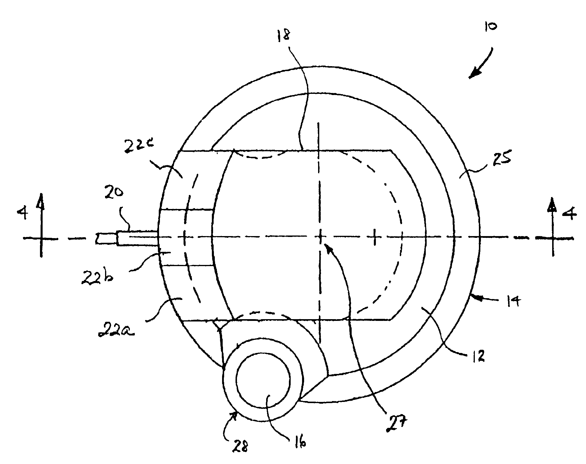
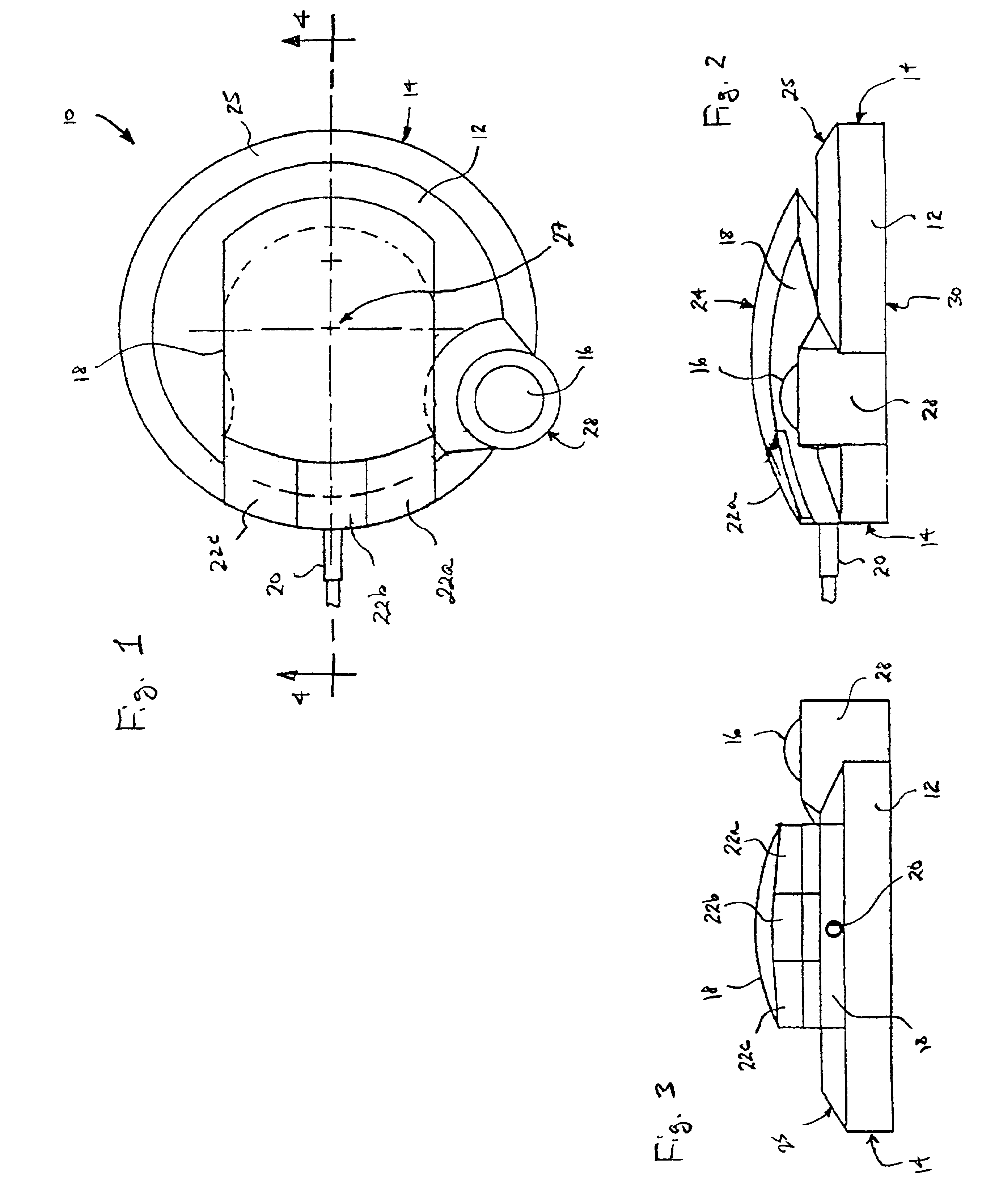
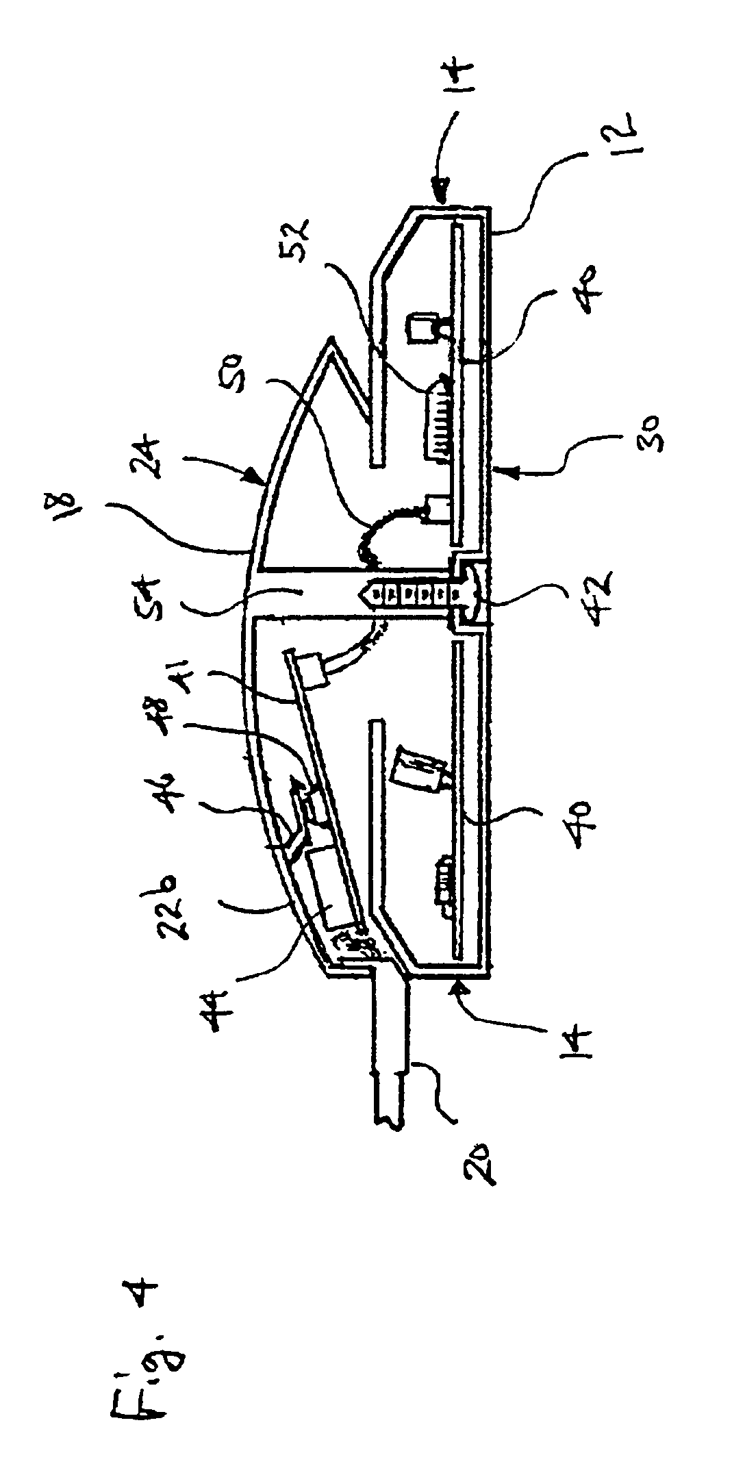
[0029]FIG. 1, FIG. 2, and FIG. 3 illustrate a top view, a side view, and a rear view, respectively, of a trackball embodiment of the present invention. Referring specifically to FIG. 1, a computer trackball pointing device 10 includes a base 12 which is substantially circular in shape and has a generally circular perimeter 14. It is preferably approximately 6 inches in diameter, weighs approximately 2 pounds, and is constructed generally of heavy duty plastic, although other dimensions are plausible. A chamfered surface 25 is formed between the top surface of base 12 and the perimeter surface 14. A trackball 16 is mounted off-center on the base 12 within a housing 28 formed on the base at a location intersecting the generally-circular perimeter surface 14. An upper section 18 is connected to the base 12 and includes, for this embodiment, three user-depressable buttons 22A, 22B and 22C formed substantially on a top surface 24 of the upper section 18. An interfac...


PUM


Abstract

A pointing device incorporates a biometric sensor at a location such that when operating the pointing device in a normal manner, a user's hand rests naturally in a position to place a finger of the user's hand in proximity to and readable by the biometric sensor. In one embodiment, a computer trackball pointing device includes a fingerprint sensor which is equally well suitable for use by either a right-handed or a left-handed user. Along with positional information from a position sensor and user selection information from at least one user-depressable button, the pointing device also conveys to an attached computer system information associated with the user's identity detected by the fingerprint sensor. Such a pointing device is well suited to both transparent verification as well as continuous verification, for if a user removes his or her hand from the natural position when using the device, the user's fingerprint will no longer be detectable by the fingerprint sensor, and the computer system to which the pointing device is attached can be alerted as to the need to re-authenticate any additional attempts at using the pointing device.

Description

CROSS-REFERENCE TO RELATED APPLICATION[0001]The present application is a continuation of U.S. patent application No. 08 / 940,553 filed Jan. 30, 2000, now U.S. Pat. No. 6,148,094 entitled, “Pointing Device with Biometric Sensor,” which claims benefit of Application No. 60 / 027,254 filed Sep. 30, 1996.[0002]This application claims the benefit under 35 U.S.C. § 119(e) of U.S. Provisional Application Ser. No. 60 / 027,254 filed Sep. 30, 1996, entitled “Controller Device” and naming David J. Kinsella as inventor, which provisional application discloses an exemplary embodiment of the present invention, and which provisional application is incorporated herein by reference in its entirety.BACKGROUND OF THE INVENTION[0003]1. Field of the Invention[0004]This invention is related to pointing devices, and more particularly to such devices providing biometric feedback to an attached electronic system.[0005]2. Description of Related Art[0006]Modern society demands that people may be identified for ma...

Claims


Application Information

Patent Timeline
Patent Type & Authority Patents(United States)
IPC IPC(8): G06K9/00G09G5/08G06F3/038H04B1/00
CPCG06F3/03543G06F3/03549G06F3/038G06F3/0383G06F21/32G06F21/83G06F2203/0336
Inventor KINSELLA, DAVID J.
Owner DALTON PATRICK ENTERPRISES
Why Eureka
Try Eureka