System, apparatus, and method for driving light emitting diodes in low voltage circuits

a technology of light-emitting diodes and low-voltage circuits, applied in the direction of electric variable regulation, process and machine control, instruments, etc., can solve the problems of large amount of undesirable heat, inconvenient operation, and inability to drive leds,

Inactive Publication Date: 2006-02-07
ADEMCO INC
View PDF5 Cites 126 Cited by
  • Summary
  • Abstract
  • Description
  • Claims
  • Application Information

AI Technical Summary

Problems solved by technology

Incandescent backlights are very bright, but generate a significant amount of undesirable heat.
One disadvantage to the EL backlighting technique, however, is that an inverter is required, which itself requires up to 50–60 mA of supply current and additional circuit board space.
Like an EL backlight, fluorescent backlights also require an inverter, but fluorescent backlights are not as sensitive to variations in supply voltage and withstand shock and vibration well.
The light provided by the LEDs tends to be rather uneven, however, and a light pipe or light diffuser is often used to create increased uniformity.
As technology progresses, however, the designer is forced to work with increasingly challenging design constraints such as power, weight, and size restrictions.
Power supply levels, for example, are particularly challenging with respect to driver circuits for the LED backlights.
The designer, therefore, is faced with the arduous task of designing LED driver circuits using power supply voltage levels that offer less than the forward operating voltage required by the LED(s).
The advantages gained by the reduction of the power supply levels often outweigh the advantages gained from using higher power supply levels for driving LEDs, and thus does not provide a practical solution.
The cost of redesign, however, may be prohibitive due to exorbitant component cost or lack of component availability.

Method used


Image

  • System, apparatus, and method for driving light emitting diodes in low voltage circuits
  • System, apparatus, and method for driving light emitting diodes in low voltage circuits
  • System, apparatus, and method for driving light emitting diodes in low voltage circuits

Examples


Embodiment Construction

[0025]In the following description, reference is made to the accompanying drawings which form a part hereof, and in which is shown by way of illustration particular embodiments in which the invention may be practiced. It is to be understood that other embodiments may be utilized, as structural and operational changes may be made without departing from the scope of the present invention.

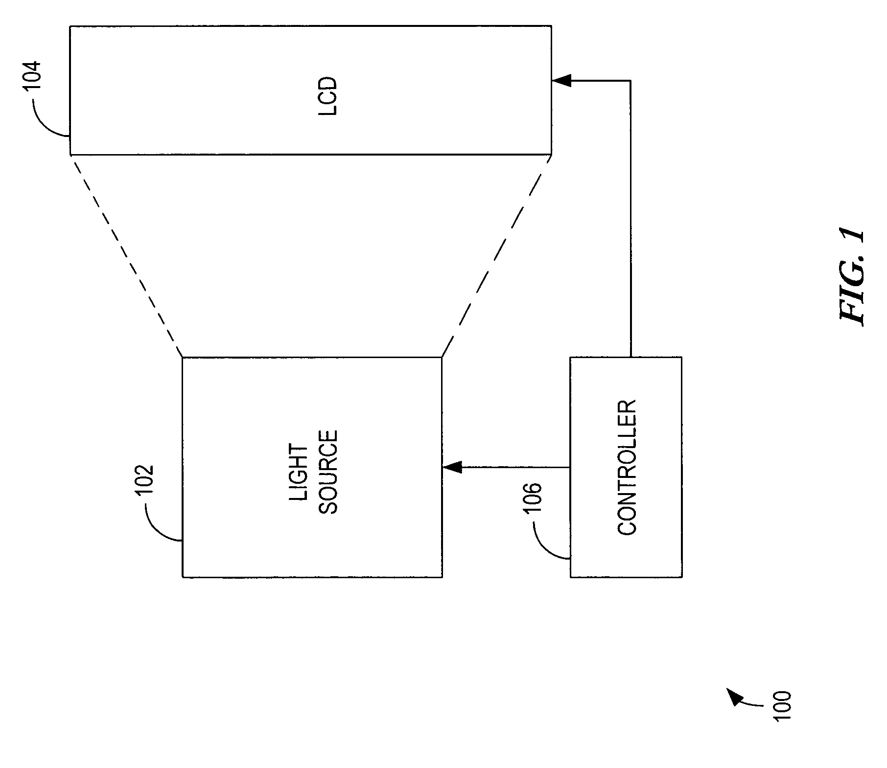
[0026]FIG. 1 is a block diagram of display 100 in accordance with the principles of the present invention. Display 100 may be incorporated into any number of devices requiring the display of information such as hand-held computing devices, Personal Digital Assistants (PDA), laptop computers, electronic instrumentation, electronic games, thermostats, etc. Display 100 includes LCD 104 having light source 102 to provide the backlighting necessary for proper illumination of LCD 104. Controller 106 provides the control and / or data signals required by light source 102 and LCD 104 to display information as m...


PUM


Abstract

A system, apparatus, and method for allowing LED operation in circuits operating with power supply levels that are below the forward voltage limits of the LED. A first level of a modulated voltage signal is applied to charge a voltage increasing component in a first phase of operation. A second level of the modulated voltage signal is then summed with the voltage stored across the voltage increasing component to provide adequate forward potential across Light Emitting Diode (LED) for illumination. The second level of modulated voltage is also used to provide a source of constant forward current to be conducted by LED when in its luminescent state.

Description

FIELD OF THE INVENTION[0001]This invention relates in general to Light Emitting Diode (LED) control, and more particularly to a system, apparatus, and method for driving the LED using a control circuit operating with a power supply lower than the forward voltage required by the LED.BACKGROUND OF THE INVENTION[0002]LEDs are used in a wide variety of applications from optical communications equipment to digital displays. In communications equipment, LEDs may be used to provide the light source required when propagating optical signal energy from one end of an optical fiber to the other end. In digital displays, for example, LEDs are becoming more pervasive for use in the backlighting that is required for Liquid Crystal Displays (LCD), or similar display units.[0003]LCDs are found in everyday use such as in laptop computers, digital clocks and watches, microwave ovens, CD players, thermostats and many other electronic devices. These devices require displays to communicate pertinent inf...

Claims


Application Information

Patent Timeline
Patent Type & Authority Patents(United States)
IPC IPC(8): G09G3/10G09G3/34H05B44/00
CPCH05B33/0815H05B45/38
Inventor HAVLIK, STEVEN M.HORNING, ERNEST F.
Owner ADEMCO INC
Why Eureka
Try Eureka