Low cost robot manipulator

a robot manipulator and low-cost technology, applied in the field of robotic manipulators, can solve the problems of high impracticality value for optical sensor fabrication or operation, low business operating cost, and inability to meet the needs of robot operators, so as to reduce business operating cost, and improve business operation.

Inactive Publication Date: 2006-02-07
THE BOEING CO
View PDF12 Cites 88 Cited by
  • Summary
  • Abstract
  • Description
  • Claims
  • Application Information

AI Technical Summary

Benefits of technology

[0007]Robots and remote manipulators have the potential to replace expensive human labor and thus reduce business operating costs, but are currently too expensive, inferior and unreliable. In one embodiment of the present invention, two single-axis MEMS inertial sensors are aligned with each joint drive axis, in the general case, one mounted on the input side and one on the output side. In the case of an input side being earth ground or having otherwise known rate an output MEMS sensor is only required. The rate or velocity resolution of each individual inertial sensor and the computed relative rate from their difference is superior to that of state of the art tachometers or position encoders based on emerging MEMS gyro measured performance. This attribute in combination with their negligible size (mm or cm across) enables robust joint servo control with better than state of the art output resolution. For example, present MEMS chip resolution now approaching 0.1 deg / h would require a position encoder with 13 million physical position resolution elements or 50 nanometer spacing on 8 inch diameter sensing ring—a highly impractical value for optical sensor fabrication or operation. This new joint sensor and method replaces the relative rate and orientation sensors at each joint of a typical robotic manipulator and further enables a lighter weigh, lower cost, lower class precision gear train and sensor system A three-axis inertial measurement unit can be used for accurate inertial navigation of the end effector. This combination of elements enables superhuman performance and reliability when used with a state of the art digital computer. Further, this system can be provided at a lower cost and lower weight than conventional joints and end effectors.
[0008]A typical robotic manipulator of the invention includes at least one joint, each joint having a drive axis and at least one microelectromechanical system (MEMS) inertial sensor aligned with at least one drive axis providing sensing of a relative position of the drive axis. The joints of the manipulator couple one or more moveable links together. An end effector can be affixed to the manipulator to perform specific tasks. The robotic manipulator can include an inertial measurement unit (IMU) coupled to end link of the manipulator for determining a position and orientation of the end effector. A controller can be used, receiving a signal for the position of the robotic manipulator from the one or more MEMS inertial sensors and controlling each joint drive axis to change the position of the robotic manipulator. An accurate, precise and inexpensive MEMS inertial sensor is a key component to implementing the present invention.

Problems solved by technology

Robots and remote manipulators have the potential to replace expensive human labor and thus reduce business operating costs, but are currently too expensive, inferior and unreliable.
For example, present MEMS chip resolution now approaching 0.1 deg / h would require a position encoder with 13 million physical position resolution elements or 50 nanometer spacing on 8 inch diameter sensing ring—a highly impractical value for optical sensor fabrication or operation.

Method used


Image

  • Low cost robot manipulator
  • Low cost robot manipulator
  • Low cost robot manipulator

Examples


Embodiment Construction

[0015]In the following description, reference is made to the accompanying drawings which form a part hereof, and which is shown, by way of illustration, several embodiments of the present invention. It is understood that other embodiments may be utilized and structural changes may be made without departing from the scope of the present invention.

1.0 Overview

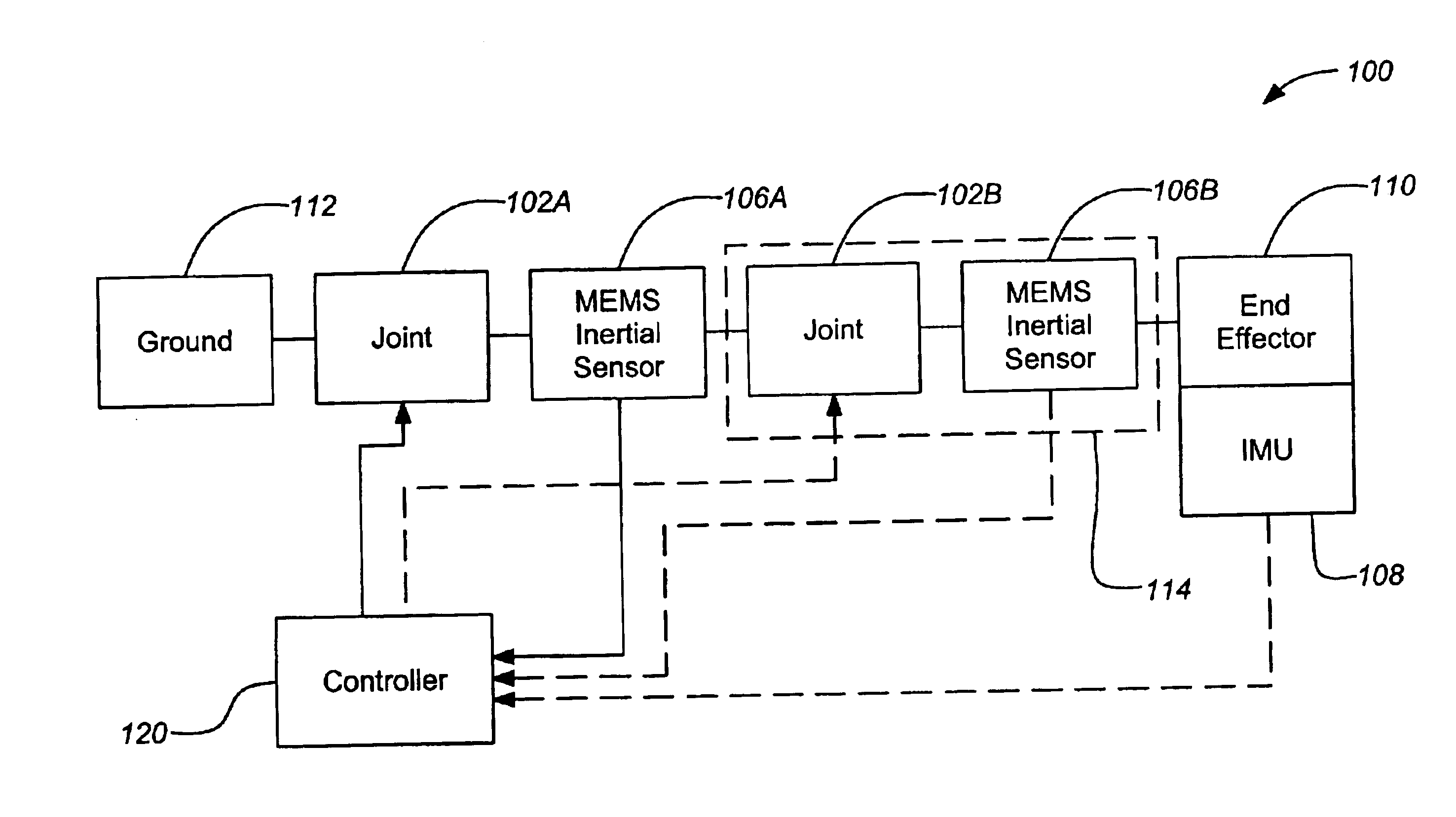
[0016]Conventional remote manipulators are controlled with a resolved rate or resolved position algorithm used to determine the desired change in end effector rate or position into a appropriate set of relative rate or position commands to each joint. In the present invention, however, MEMS gyro inertial rate measurements from joint output and input are subtracted to derive the joint relative rate required for joint servo control. Integration of this derived relative rate provides the relative orientation of the joint output relative to joint input.

[0017]Recently developed MEMS microgyros have a rate resolution of approximately 1...


PUM


Abstract

The present invention discloses a robotic manipulator, comprising at least one joint, each joint having a drive axis and at least one microelectromechanical system (MEMS) inertial sensor aligned with at least one drive axis providing sensing of a relative position of the drive axis. The robotic manipulator can include an inertial measurement unit (IMU) coupled to the robotic manipulator for determining the end effector position and orientation. A controller can be used, receiving a signal from at least one MEMS inertial sensor and controlling at least one joint drive axis in response to the signal to change the relative position of the joint drive axis. Rate information from MEMS sensors can be integrated to determine the position of their respective drive axes.

Description

BACKGROUND OF THE INVENTION[0001]1. Field of the Invention[0002]The present invention relates to robotic manipulators, and in particular to cost-effective sensing systems for robotic manipulator. More particularly, this invention relates to inertial sensing applied to robotic manipulators.[0003]2. Description of the Related Art[0004]Currently, robots and remote manipulators with superior and reliable closed loop control are expensive because they employ multiple joints with expensive joint servo controllers. The high cost of motion sensors is a principal reason for the expense and weight of the joint servos of robotic manipulators and as a consequence the utility of robots versus other means of delivery or production, e.g. human labor. Typically, six joints are utilized with a tachometer and a position encoder employed at each joint, often at the input of a heavy, mechanically stiff, high class gear reduction system to increase output torque capability while maintaining output posit...

Claims


Application Information

Patent Timeline
Patent Type & Authority Patents(United States)
IPC IPC(8): B25J15/02G05B19/04B25J9/16G05B19/27
CPCB25J9/1694G05B19/27G05B2219/40596G05B2219/40547G05B2219/37134
Inventor CHALLONER, A. DORIAN
Owner THE BOEING CO
Why Eureka
Try Eureka