Amplifier with a universal automatic gain control circuit

a gain control and automatic gain control technology, applied in the field of amplifiers, can solve the problems that the peak detection of an agc circuit does not provide useful or accurate information

Active Publication Date: 2006-02-07
CISCO TECH INC
View PDF10 Cites 6 Cited by
  • Summary
  • Abstract
  • Description
  • Claims
  • Application Information

AI Technical Summary

Problems solved by technology

More specifically, the DC voltage values of the QAM modulated signals include complex, multi-level data having peak val...

Method used


Image

  • Amplifier with a universal automatic gain control circuit
  • Amplifier with a universal automatic gain control circuit
  • Amplifier with a universal automatic gain control circuit

Examples


Embodiment Construction

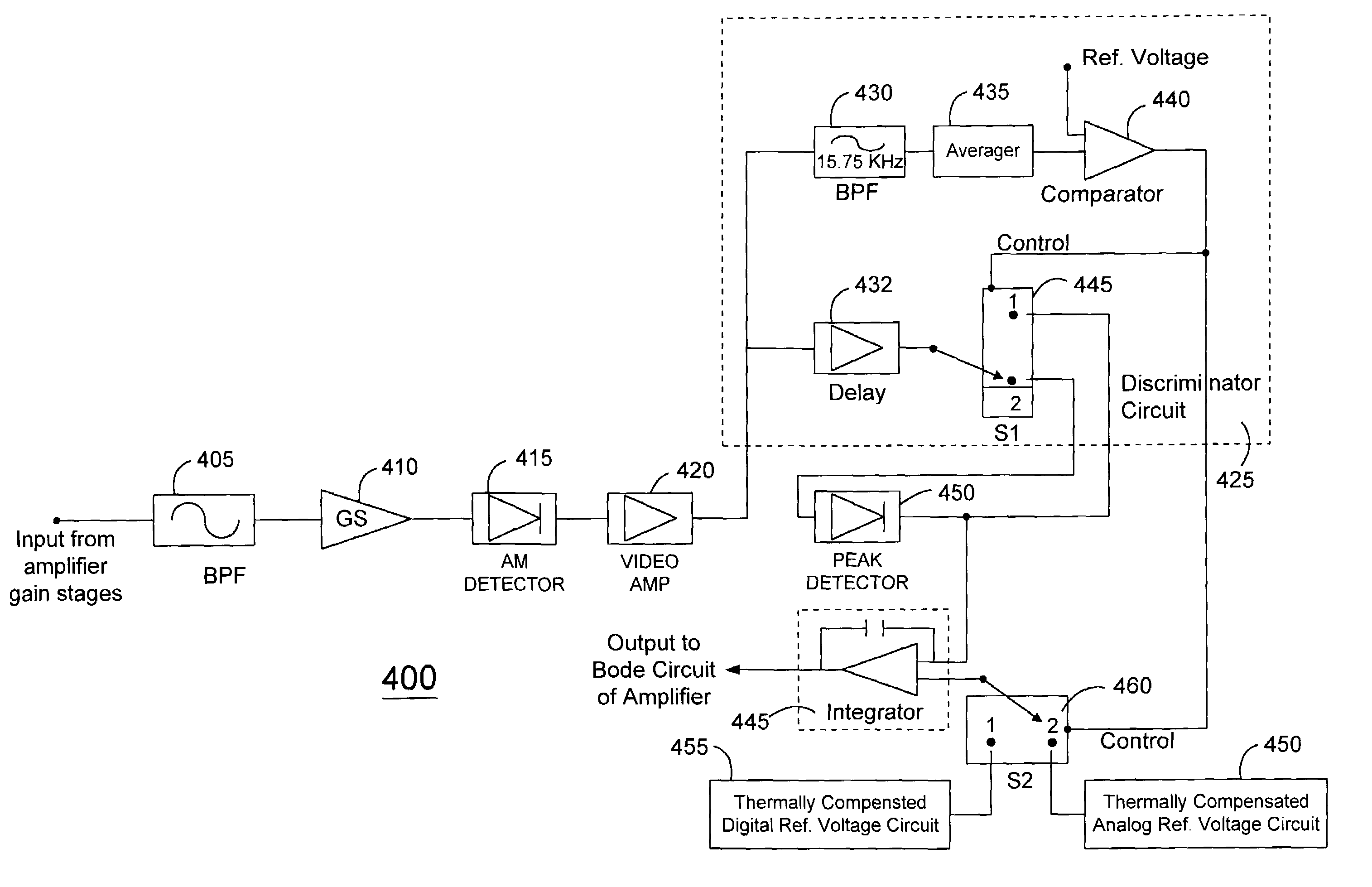
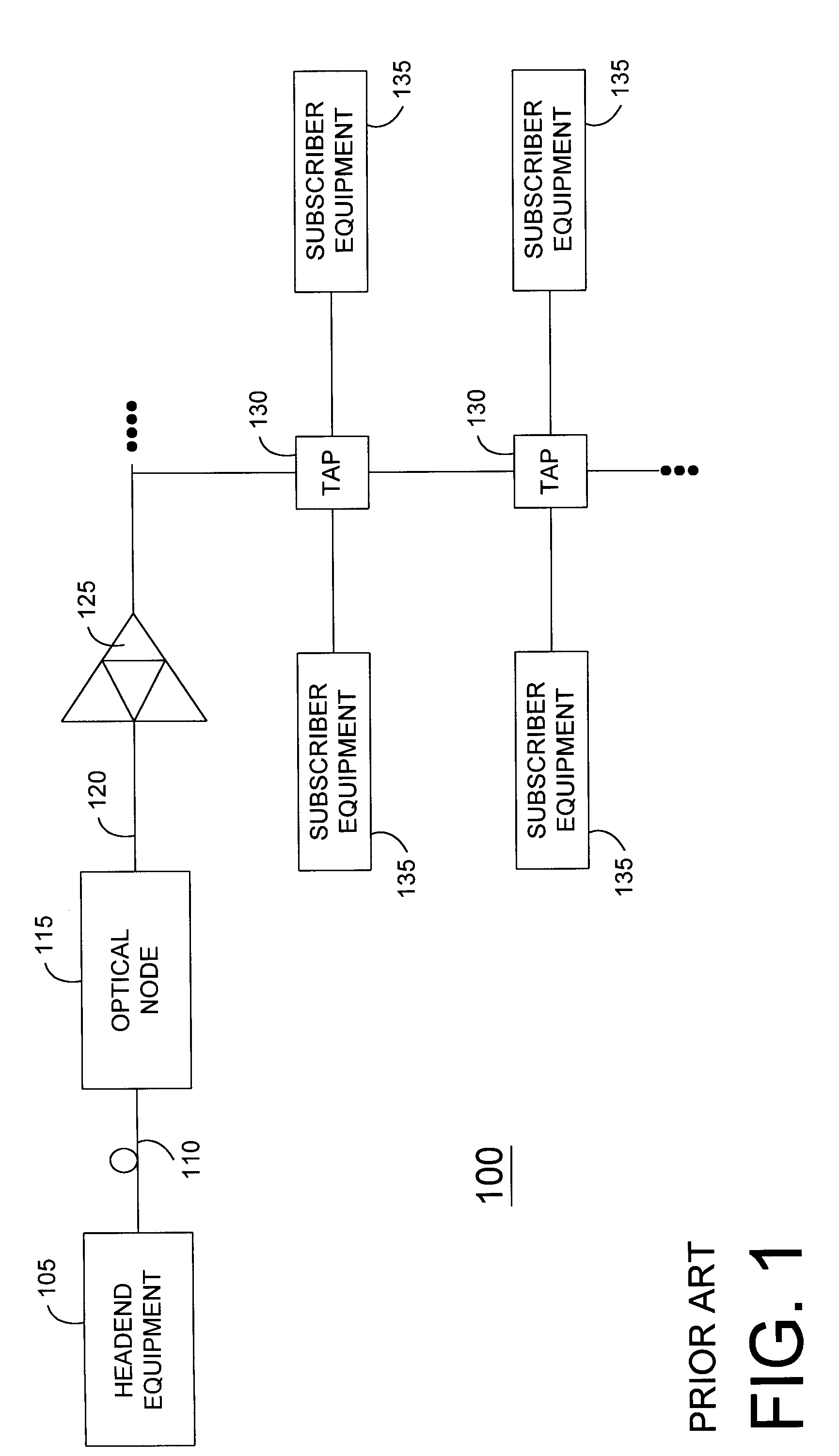
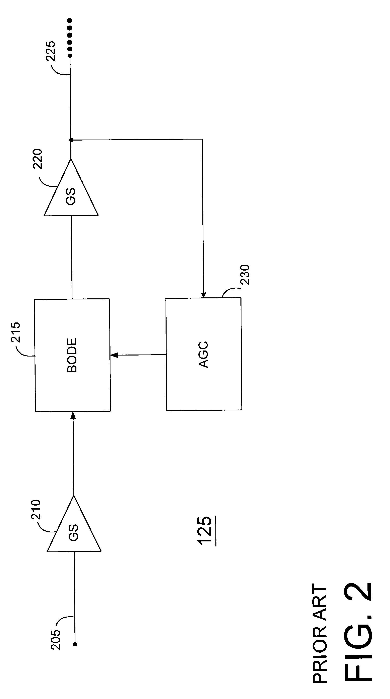
[0015]As briefly mentioned in the Background of the Invention, communication systems often include amplifiers for boosting signal levels as signals are transmitted to remote subscribers. These amplifiers typically include automatic gain control (AGC) circuits for controlling signal levels, but conventional AGC circuits are not suitable for use with both analog and digital pilot signals. Instead, conventional AGC circuits are limited to processing analog input signals. With cable television systems migrating to a digital format, the amplifiers require an alternative AGC circuit to monitor and control amplifier gain using a digital input signal in addition to conventional analog input signals.

[0016]An advantage of the present invention is that an AGC circuit, which is depicted in FIG. 4, can be provided to discriminate between an analog forward signal and a digital forward signal and to use either for controlling gain levels within an amplifier. One of the functions of an AGC circuit ...


PUM


Abstract

An amplifier (125) includes a gain stage (210) for amplifying a signal received by the amplifier (125). The amplifier (125) also includes an AGC circuit (400) that adjusts the amplification of the gain stage (210) and that includes a comparator (440) for determining whether the input signal is one of a digital pilot signal and one of an analog pilot signal. The AGC circuit (400) processes both digital and analog pilot signals and automatically adjusts the processing method depending upon the type of pilot signal.

Description

FIELD OF THE INVENTION[0001]This invention relates generally to amplifiers, and more specifically to automatic gain control (AGC) circuits.BACKGROUND OF THE INVENTION[0002]A communication system 100, such as a two-way cable television system, is depicted in FIG. 1. The communication system 100 includes headend equipment 105 for generating forward signals that are transmitted in the downstream direction along a communication medium, such as a fiber optic cable 110, to an optical node 115 that converts optical signals to radio frequency (RF) signals. The RF signals are further transmitted along another communication medium, such as coaxial cable 120, and are amplified, as necessary, by one or more distribution amplifiers 125 positioned along the communication medium. Taps 130 included in the cable television system split off portions of the forward signals for provision to subscriber equipment 135, such as set top terminals, computers, and televisions. In a two-way system, the subscri...

Claims


Application Information

Patent Timeline
IPC IPC(8): H04N5/44H03G3/00H04N5/52H04N7/10
CPCH03G3/005H04N5/52H04N7/102
Inventor AL-ARAJI, SALEHRITCHIE, JR., JOHN A.
Owner CISCO TECH INC
Why Eureka
Try Eureka