System and method for remote retrofit identification of energy consumption systems and components

a technology for retrofitting and energy consumption systems, applied in the field of energy systems, can solve the problems of high cost and time consumption of obtaining the required information, and achieve the effect of increasing efficiency and increasing energy usage efficiency

Active Publication Date: 2006-02-07
TEXAS A&M UNIVERSITY
View PDF14 Cites 73 Cited by
  • Summary
  • Abstract
  • Description
  • Claims
  • Application Information

AI Technical Summary

Benefits of technology

[0009]Another technical advantage of the present invention includes identifying operating parameters of energy consumption systems and/or components associated with a facility, and determining whether modifications to the operating parameters should be performed to increase efficiency. For example, after identifying particular energy consumption systems and devices

Problems solved by technology

Obtaining the required information, however, generally requires access to the facility and/or the energy consumptio

Method used


Image

  • System and method for remote retrofit identification of energy consumption systems and components
  • System and method for remote retrofit identification of energy consumption systems and components
  • System and method for remote retrofit identification of energy consumption systems and components

Examples


Embodiment Construction

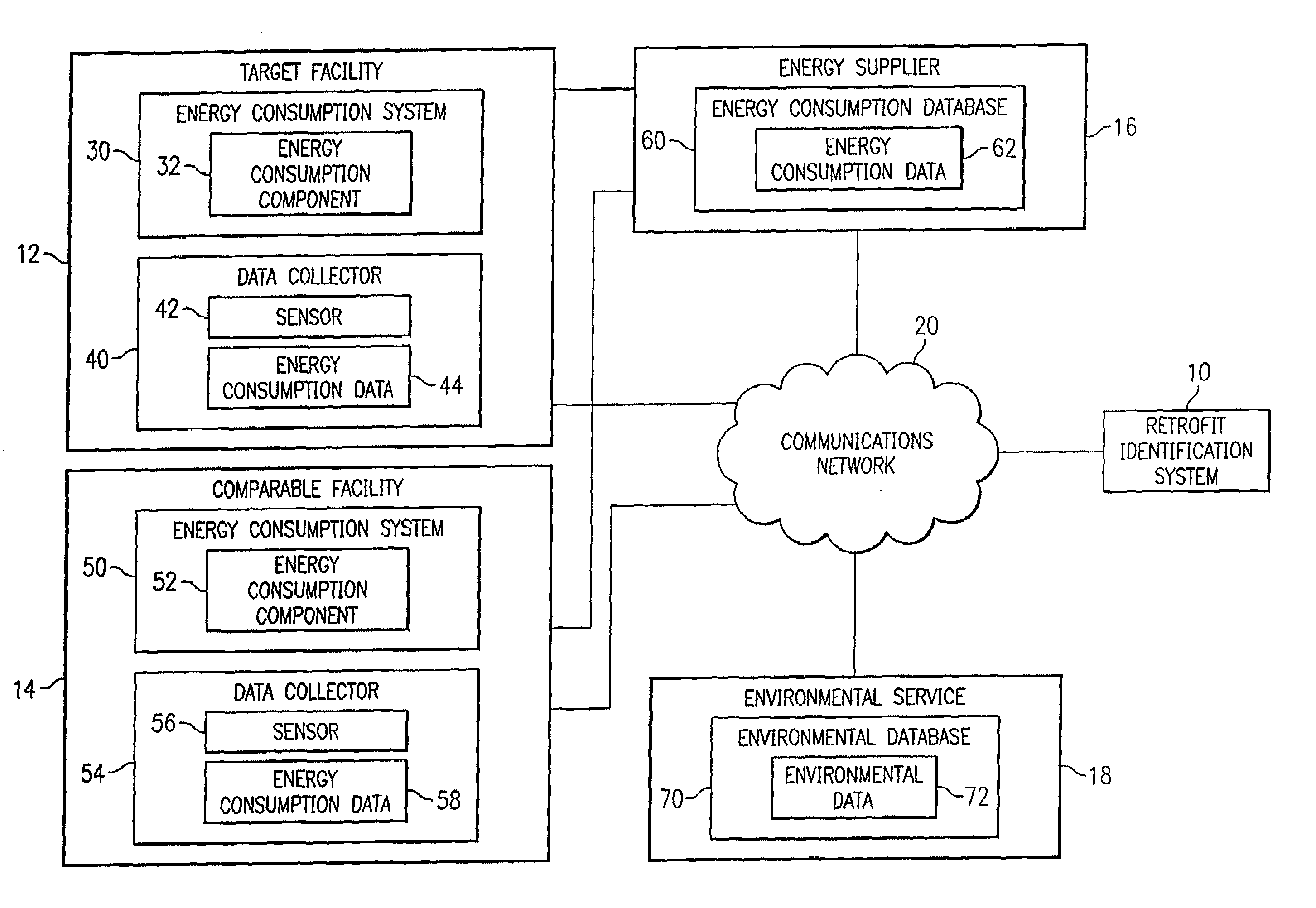
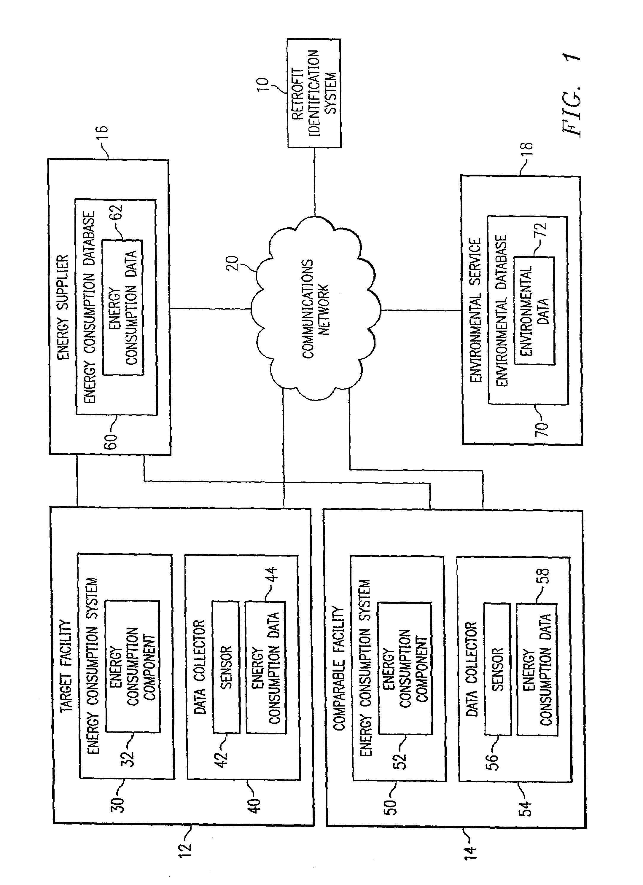
[0015]FIG. 1 is a block diagram in which a system 10 for remote retrofit identification of energy consumption systems and components in accordance with an embodiment of the present invention is illustrated. In the illustrated embodiment, system 10 is coupled to a target facility 12, a comparable facility 14, an energy supplier 16, and an environmental service 18 via a communications network 20. The communications network 20 may be different networks, or the same network, and may include any Internet, intranet, extranet, or similar communication network. The communications network 20 provides an electronic medium for transmitting and receiving information between the system 10 and facilities 12 and 14, the environmental service 18, and the energy supplier 16. However, other electronic and non-electronic modes of communication may also be used for transmitting and receiving information between the system 10 and the facilities 12 and 14, the environmental service18, and the energy supp...


PUM


Abstract

A method for remote energy consumption system retrofit identification for a facility includes receiving energy consumption data associated with the facility, generating facility data associated with the facility, and receiving external variable data associated with the facility corresponding to the energy consumption data. The method also includes generating a first energy consumption model based on the facility data, the energy consumption data, and the external variable data. The method also includes generating a second energy consumption model based on the facility data and the external variable data. The method further includes determining energy consumption efficiency for the facility using the first and second energy consumption models and identifying a retrofit of an energy consumption system of the facility based on the energy consumption efficiency.

Description

TECHNICAL FIELD OF THE INVENTION[0001]This invention relates in general to the field of energy systems and, more particularly, to a system and method for remote retrofit identification of energy consumption systems and components.BACKGROUND OF THE INVENTION[0002]Schools, office buildings, homes, department stores, hospitals, and other types of facilities consume energy in varying amounts using a variety of different types of systems and components. For example, energy consumption systems and components may be used for environmental control, such as heating and cooling, for lighting, for security system applications, for computer usage applications, and for a variety of other energy consumption applications corresponding to the particular type of facility.[0003]Because the types of facilities vary to a generally large degree, the energy usage associated with each type of facility also varies to a generally large degree. For example, energy consumption systems and components associate...

Claims


Application Information

Patent Timeline
IPC IPC(8): G06F17/10
CPCG06Q50/06G05B15/02
Inventor CULP, CHARLES H.CLARIDGE, DAVID E.HABERL, JEFFREY S.TURNER, WILLIAM D.
Owner TEXAS A&M UNIVERSITY
Why Eureka
Try Eureka