Cooling device

a cooling device and cooling device technology, applied in the field of cooling systems, can solve the problems of increasing the internal temperature of the enclosure, affecting the efficiency of cooling devices, so as to reduce the number of equipment installed, reduce the time, and simplify the setting work

Inactive Publication Date: 2006-02-14
MITSUBISHI ELECTRIC CORP
View PDF18 Cites 59 Cited by
  • Summary
  • Abstract
  • Description
  • Claims
  • Application Information

AI Technical Summary

Benefits of technology

[0026]The invention set forth renders small an equipment installation space required by the cooling system. Further, there can be achieved a reduction in the number of pieces of equipment installed, simplification of setting work, and a reduction in the time required for examining installation positions for the equipment required to be set in the vicinity of internal heat-generation equipment. Moreover, projections and indentations in the cooling system become smaller, thereby enhancing the appearance of the cooling system.
[0027]Switching between cooling modes is performed through appropriate control operation, thereby reducing the power c

Problems solved by technology

However, since the cooling system becomes inoperative, the internal temperature of the enclosure 53 increases.
Setting the auxiliary cooling device indoor unit in the vicinity of an air outlet of heat-generating equipment results in a greater effect but poses a problem of limitations of space.
Moreover, a plurality of pieces of equipment are disposed outside the enclosure, which induces projections a

Method used


Image

  • Cooling device
  • Cooling device
  • Cooling device

Examples


first embodiment

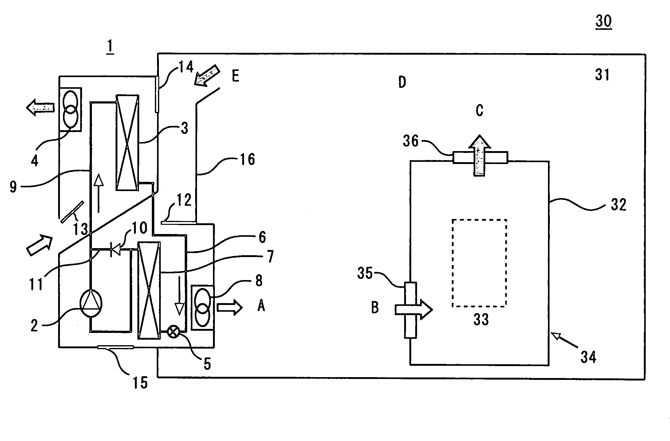
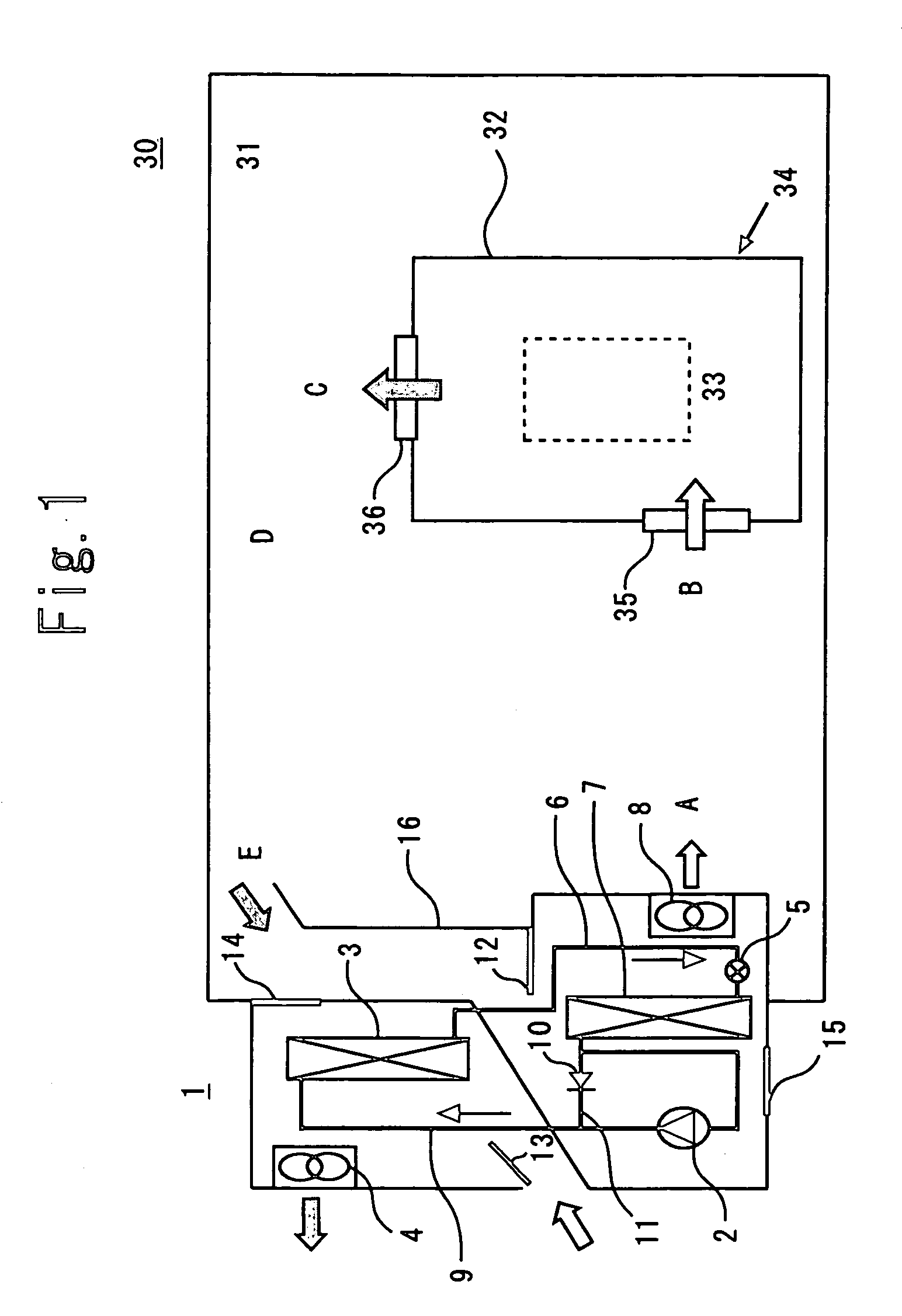
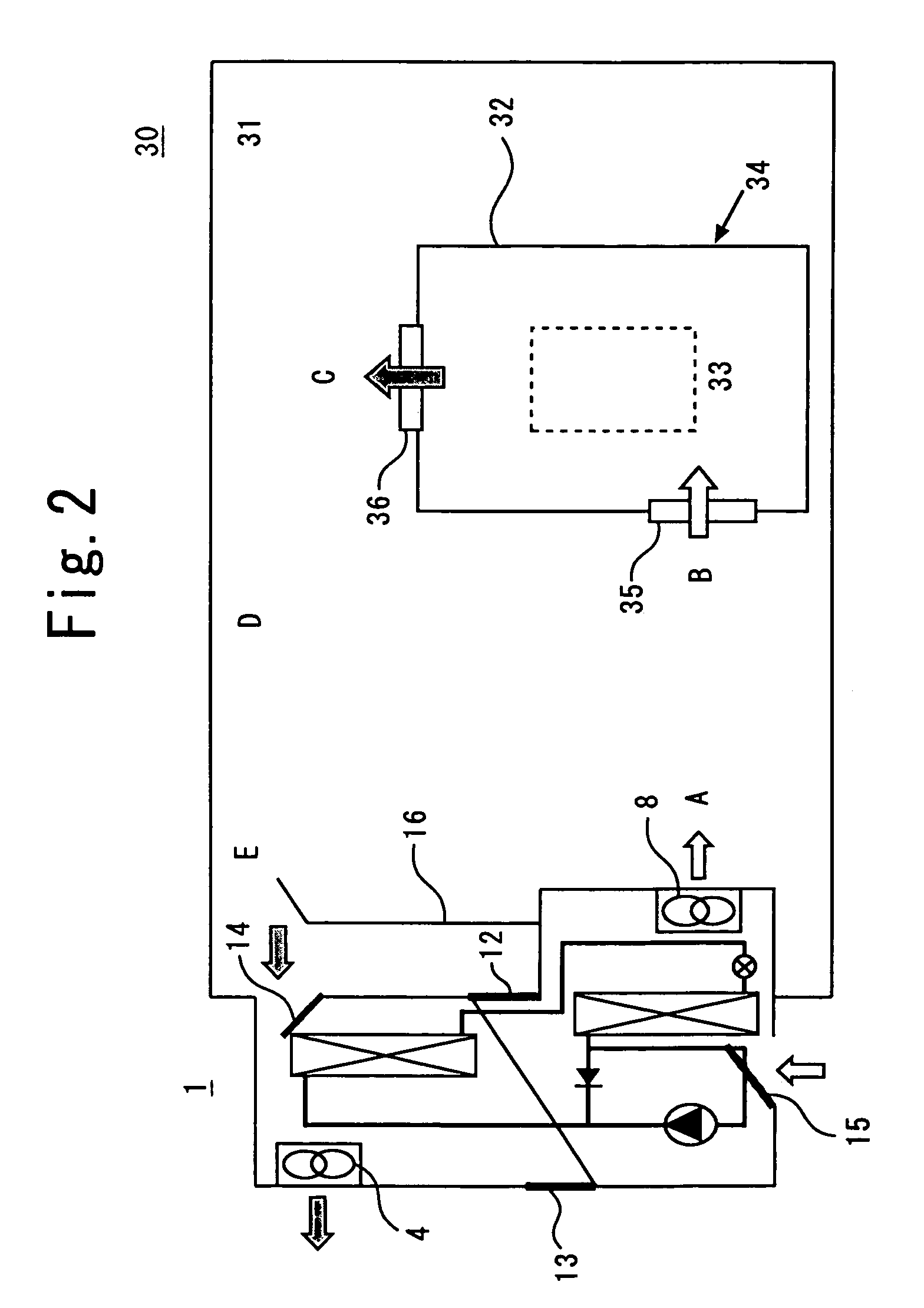
[0038]FIGS. 1 and 2 are schematic block diagrams showing a cooling system according to a first embodiment of the invention. FIG. 1 shows a refrigerant forced circulation mode and a refrigerant natural circulation mode; that is, an operating state in a non-ventilation mode. FIG. 2 shows an operating state of the cooling system in a ventilation mode.

[0039]Throughout the drawings, reference numeral 1 designates a cooling system; 2 designates a compressor; 3 designates a condenser; 4 designates an outdoor fan; 5 designates an expansion valve, e.g., an electronic expansion valve; 6 designates a liquid pipe; 7 designates an evaporator; 8 designates an indoor fan; 9 designates a gas pipe; 10 designates an open-close valve, e.g., a check valve; and 11 designates a compressor bypass pipe. Reference numeral 12 designates an indoor air inlet port; 13 designates an outside air inlet port; 14 designates a ventilation indoor air inlet port; 15 designates a ventilation outside air inlet port; and ...

second embodiment

[0060]FIGS. 3 and 4 are schematic block diagrams showing a cooling system of a second embodiment of the invention. FIG. 3 shows the refrigerant natural circulation operation and the refrigerant forced circulation operation; that is, the non-ventilation operation. FIG. 4 shows a ventilation operation. In FIGS. 3 and 4, those elements which are identical with or correspond to those shown in FIG. 1 are assigned the same reference numerals, and their detailed explanations are omitted.

[0061]Throughout the drawings, reference numeral 17 designates a controller; 18 designates an outside air temperature sensor serving as first temperature detection means; 19 designates a room temperature sensor serving as second temperature detection means; 20 designates temperature detection means; 21 designates a fireproof damper; 22 designates a fireproof damper; 23 designates an intake hood; 24 designates a blowout hood; and 25 designates a battery.

[0062]The cooling system 1 is equipped with the control...

third embodiment

[0077]FIG. 7 is a schematic block diagram showing a cooling system according to a third embodiment of the invention. In FIG. 7, those elements which are identical with or correspond to those shown in FIG. 1 are assigned the same reference numerals, and their detailed explanations are omitted.

[0078]As shown in FIG. 7, the cooling system of the embodiment is separately equipped with a refrigerant circuit for refrigerant forced circulation operation and a refrigerant circuit for refrigerant natural circulation operation. The two refrigerant circuits share the outdoor fan and the indoor fan.

[0079]Operation of the cooling system will now be described by reference to FIG. 8.

[0080]According to the chart shown in FIG. 8, the cooling system performs control operation on the basis of the temperature obtained by the outside air temperature sensor (not shown) and the room temperature sensor (not shown). Specifically, when the temperature of the outside air is higher than the room temperature, t...


PUM


Abstract

A cooling system that has a heat exchanger which is housed in one enclosure and is constituted of a plurality of heat exchange modes, and the heat exchanger includes a refrigerant forced circulation mode, a refrigerant natural circulation mode, and a ventilation mode. A temperature detector performs switching to an optimal mode, to thereby cool the inside of the enclosure of a housing accommodating equipment including a heat-generating component.

Description

FIELD OF THE INVENTION[0001]The invention relates to a cooling system, and more particularly, to a cooling system to be provided in an enclosure of a housing which accommodates a heat-generating equipment having a built-in sensible-heat-generating element, such as a substrate.BACKGROUND ART[0002]In relation to housing which is an object of cooling, heat-generating equipment is generally housed in a sealed enclosure. The enclosure has a narrow space which inhibits entry of a person. Equipment housed in the enclosure has heat-generating components and hence is cooled appropriately.[0003]A cooling system described in Japanese Patent Application Laid-Open No. 041503 / 2001 is mentioned as a cooling system for cooling the inside of such an enclosure. FIG. 9 shows the cooling system.[0004]As shown in FIG. 9, an enclosure cooling system 51 of a housing 52 is configured to cool the inside of an enclosure 53 of the housing 52 that forms a closed space, by means of an auxiliary cooling device i...

Claims


Application Information

Patent Timeline
IPC IPC(8): F25D23/12F25D31/00F25D19/02H05K7/20
CPCF24F1/022F25D19/02H05K7/20609F25D2700/14F25D2700/12F25D31/00
Inventor KAMEYAMA, SUSUMUSESHIMO, YUHATAMURA, YASUFUMIINO, MASAOKIKOBAYAKAWA, HIROYUKIENOMOTO, TOSHIHIKOSAITOU, MAKOTO
Owner MITSUBISHI ELECTRIC CORP
Why Eureka
Try Eureka