Dispenser and apparatus and method for filling a dispenser

a dispenser and dispenser technology, applied in the field of dispensers, can solve the problems of defective dispensers, high process and equipment costs, and time-consuming filling process, and achieve the effect of more defective dispensers than otherwise desired

Active Publication Date: 2006-02-14
MAEJ LLC ODONNELL & TESSITORE
View PDF159 Cites 70 Cited by
  • Summary
  • Abstract
  • Description
  • Claims
  • Application Information

AI Technical Summary

Benefits of technology

[0045]sealing the pump and dispensing valve from the storage chamber during filling of the storage chamber to prevent a flow of fluid through the dispensing valve during filling of the storage chamber.
[0047]One advantage of the present invention is that the dispenser may be assembled, sealed and sterilized empty. Then, the sterilized dispenser may be filled with a sterile fluid or other substance through the filling valve and without disassembling the dispenser.

Problems solved by technology

One of the drawbacks of such prior art dispensers, and processes and equipment for filling such dispensers, is that the filling process is time consuming, and the processes and equipment are expensive.
Further, the relatively complex nature of the filling processes and equipment can lead to more defectively filled dispensers than otherwise desired.
Although this resealable stopper, apparatus and method overcome many of the drawbacks and disadvantages associated with prior art equipment and processes for sterile filling, in certain instances it may not be desirable to employ a resealable stopper, a needle for piercing the stopper, and / or a laser for resealing the penetrated region of a stopper.

Method used


Image

  • Dispenser and apparatus and method for filling a dispenser
  • Dispenser and apparatus and method for filling a dispenser
  • Dispenser and apparatus and method for filling a dispenser

Examples


Embodiment Construction

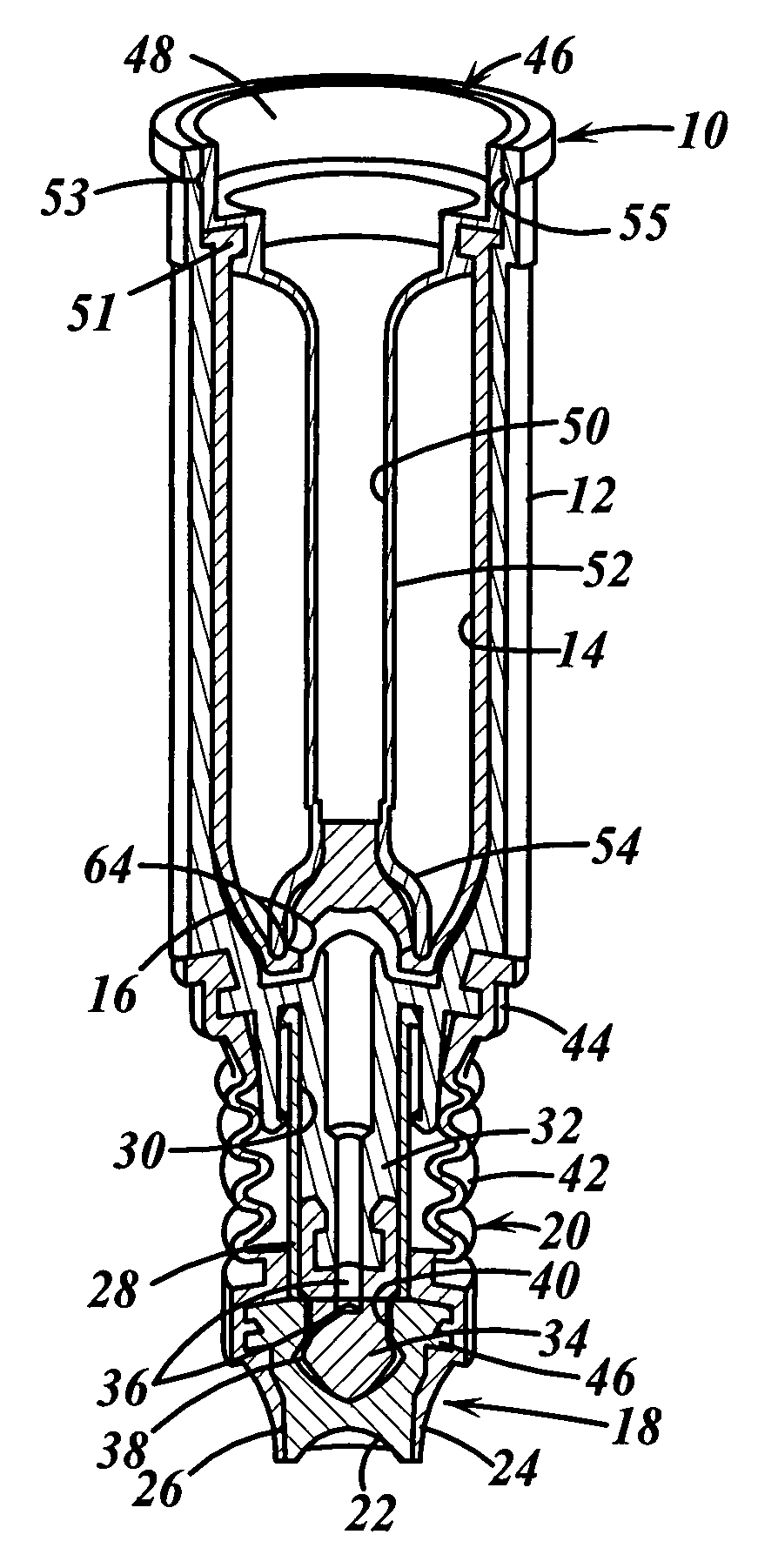
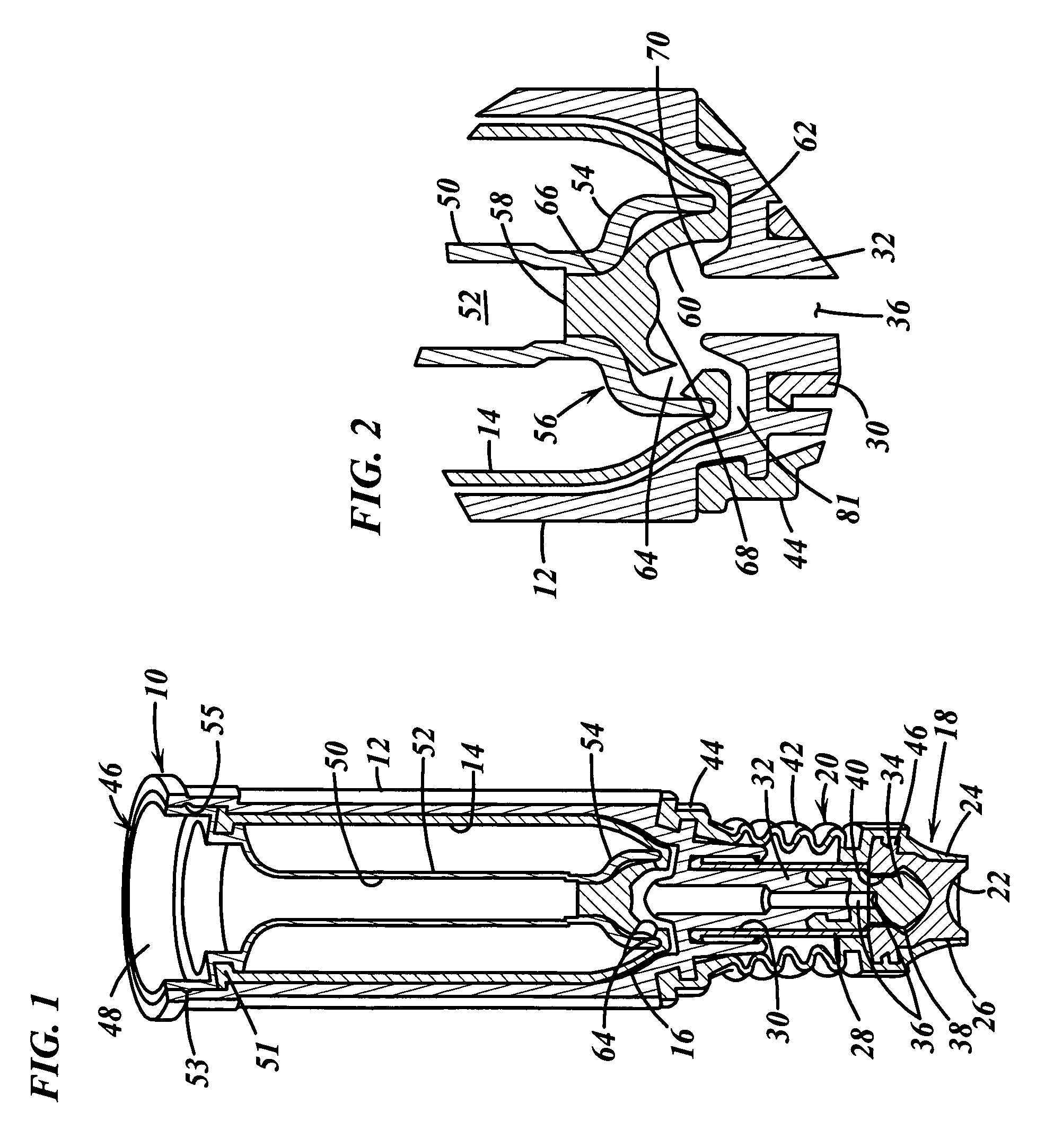
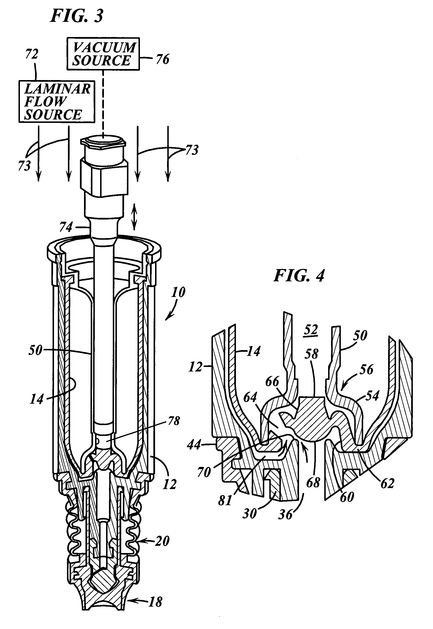
[0049]In FIG. 1, a dispenser embodying the present invention is indicated generally by the reference numeral 10. The dispenser 10 comprises a rigid vial or body 12, a flexible bladder 14 mounted within the rigid vial 12, and a variable-volume storage chamber 16 formed between the vial and bladder for receiving therein a fluid or other substance, such as a medicament. The dispenser 10 further comprises a dispensing nozzle 18 and a pump 20 coupled in fluid communication between the dispensing nozzle 18 and the storage chamber 16 for pumping metered doses of the fluid or other substance from the storage chamber 16 through the dispensing nozzle.

[0050]The dispensing nozzle 18 includes a relatively rigid valve seat 22 and a flexible valve cover 24 mounted over the valve seat and defining an axially elongated, annular seam 26 therebetween. As described further below, the pump 20 forces a metered dose of fluid or other substance at sufficient pressure to open the valve (the “valve opening p...


PUM

PropertyMeasurementUnit
volumeaaaaaaaaaa
flexibleaaaaaaaaaa
forcesaaaaaaaaaa

Abstract

A dispenser for holding multiple doses of fluids or other substances, and for dispensing the substances, has a vial, a flexible bladder received within the vial, and a variable volume storage chamber formed between the bladder and vial. A filling valve is coupled in fluid communication with the storage chamber and defines (1) a normally closed, fluid-tight position hermetically sealing the storage chamber from the ambient atmosphere, and (2) an open position allowing the passage of fluid through the valve both to evacuate the storage chamber and to introduce fluid through the valve to fill the storage chamber. A pump is coupled in fluid communication with the storage chamber for pumping fluids out of the storage chamber. A dispensing valve is coupled in fluid communication with the pump and defines (1) a normally closed, fluid-tight position preventing the passage of fluid out of the dispenser, and (2) an open position for dispensing pumped fluid therethrough. The sealed, empty dispenser is sterilized, such as by applying gamma radiation thereto. Then, the sterilized, sealed, empty dispenser is filled with fluid by engaging the filling valve with an evacuating / dispensing member to evacuate the storage chamber, and by introducing fluid from the filling member through the open filling valve and into the storage chamber. The filling member is withdrawn from the valve, and a spring moves the valve to a closed position to hermetically seal the fluid within the dispenser.

Description

CROSS-REFERENCE TO RELATED PRIORITY APPLICATIONS[0001]This application claims priority to U.S. application Ser. No. 60 / 469,677, filed May 12, 2003, titled “Dispenser and Apparatus and Method for Filling a Dispenser”; and U.S. application Ser. No. 60 / 471,592, filed May 19, 2003, titled “Dispenser and Apparatus and Method for Filling a Dispenser”, and U.S. application Ser. No. 60 / 488,355, filed Jul. 17, 2003, titled “Piston-Type Dispenser with One-Way Valve for Storing and Dispensing Metered Amounts of Substances, and Pivoting Cover for Covering Dispensing Portion Thereof”, and U.S. application Ser. No. 60 / 539,814, filed Jan. 27, 2004, entitled “Piston-Type Dispenser with One-Way Valve for Storing and Dispensing Metered Amounts of Substances”, the disclosures of which are hereby expressly incorporated by reference as part of the present disclosure.FIELD OF THE INVENTION[0002]The present invention relates to dispensers for containing and dispensing fluids and other substances, such as ...

Claims


Application Information

Patent Timeline
Patent Type & Authority Patents(United States)
IPC IPC(8): B65B1/04A61MB65B3/30
CPCA61J1/00A61J1/1443B65D83/62B65B31/044B65D83/425B65B3/30
Inventor PY, DANIELCHAN, JULIAN V.
Owner MAEJ LLC ODONNELL & TESSITORE
Why Eureka
Try Eureka