Locator bracket for the lower frame assembly of a blanking tool

a technology of a lower frame and a blanking tool, which is applied in the direction of metal-working equipment, metal-working equipment, thin material handling, etc., can solve the problems of not always “square” outer frames and grids that cannot always be positioned with high precision within outer frames

Inactive Publication Date: 2006-02-14
BLANKING SYST
View PDF15 Cites 29 Cited by
  • Summary
  • Abstract
  • Description
  • Claims
  • Application Information

AI Technical Summary

Benefits of technology

[0007]Yet another object of the invention is to provide a frame assembly for a lower blanking tool which is easy to assemble, compatible with standard blanking operation machinery, and relatively inexpensive.
[0009]As noted previously, the lower blanking tool must be properly positioned with respect to a pull-out frame so that the grid supported by the frame assembly of the lower blanking tool is properly positioned with respect to both the upper tool and the carton blank stacking mechanism. In order to position the lower blanking tool precisely with respect to the pull-out frame, the present invention provides a locator bracket mounted on a side rail of the lower blanking tool having a spring member projecting therefrom which is releasably engageable within a spring receiving groove formed in a cross rail of the pull-out frame. The locator bracket includes a datum member having an abutment surface which is engageable with an inner surface of the cross rail of the pull-out frame which aids in positioning the lower blanking tool with respect to the pull-out frame. The locator bracket thus releasably interconnects the lower blanking tool on the pull-out frame.

Problems solved by technology

Unfortunately, due to manufacturing tolerances, ineffective clamping devices and the like, outer frames are not always “square” with respect to the pull-out frame.
In addition, the grid may not always be positioned with high precision within the outer frame since the clamping pieces which hold the lower tool onto the pull-out frame can move slightly during assembly and thus alter the desired position of the grid.

Method used


Image

  • Locator bracket for the lower frame assembly of a blanking tool
  • Locator bracket for the lower frame assembly of a blanking tool
  • Locator bracket for the lower frame assembly of a blanking tool

Examples


Embodiment Construction

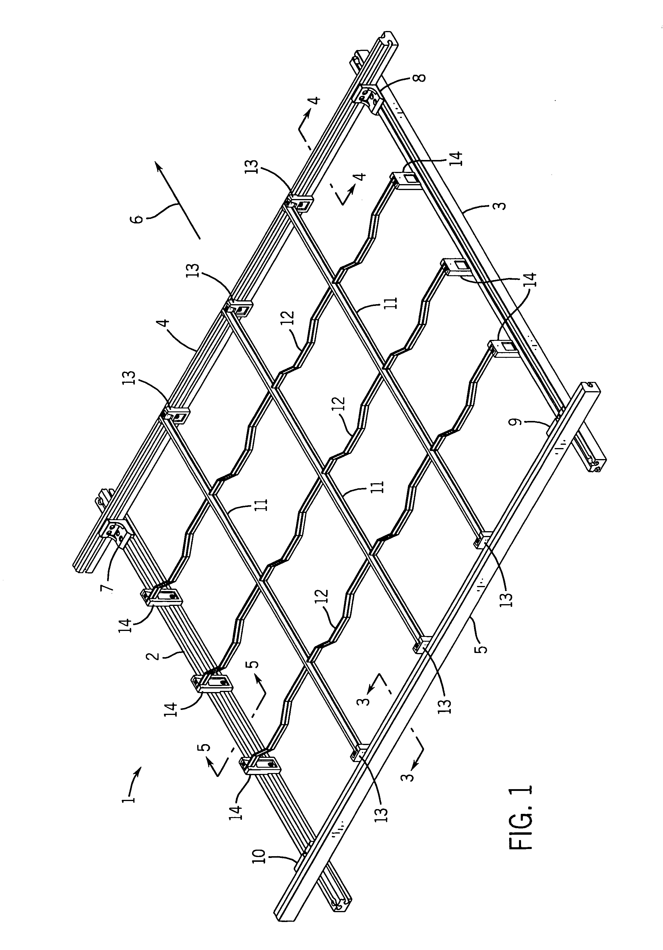
[0028]Referring now to the drawings, FIG. 1 illustrates a lower frame assembly generally designated by the numeral 1 which is used in a blanking tool of a die cutting machine for converting or processing a sheet of paper material into a carton blank. These machines are well known in the art and are used to cut one or several blanks into each sheet of paper material which, after folding and gluing, may be formed into cartons or boxes. As is conventional, the sheets of paper material move in a substantially horizontal plane within the machine and are carried through various sequences of printing, cutting, embossing, creasing, waste stripping and / or blanking stations.

[0029]The die cutting machine usually is formed by a series of stations with the first station being a starting position or input station in which the sheets, which may be preprinted if desired, are taken one by one from the top of a stack to a feed table where they are placed in position against frontal and side guides. T...


PUM

PropertyMeasurementUnit
angleaaaaaaaaaa
angleaaaaaaaaaa
angleaaaaaaaaaa

Abstract

A bracket for properly locating a lower blanking tool with respect to a pull-out frame during a blanking operation in a carton die cutting machine. The bracket is mounted on the inner side of a side rail for the lower blanking tool and includes a projecting spring member releasably engageable within a groove formed in the top side of a corresponding cross rail of the pull-out frame. The bracket also includes a projecting datum member engageable with the inner side of the pull-out frame's cross rail to aid in positioning the lower blanking tool on the pull-out frame.

Description

BACKGROUND OF THE INVENTION[0001]The present invention relates to die cutting machines for making carton blanks, and more particularly to a bracket for properly locating a lower blanking tool with respect to a pull-out frame during a blanking operation in a carton die cutting machine.[0002]In the manufacture of cartons, small sheets of paper material having specific profiles are cut out of larger sheets of paper material. These smaller sheets are known as carton blanks which, in turn, are formed into cartons and / or boxes. The blanks are formed during a process known as a blanking operation in a die cutting machine.[0003]In a die cutting machine, the blanks are cut, but not removed from a large sheet of paper material. After the blanks have been cut, the sheet is moved downstream in the die cutting machine to a blanking station where the sheet is positioned over a lower tool or frame assembly for support. The lower tool or frame assembly includes an outer frame and an inner grid havi...

Claims


Application Information

Patent Timeline
Patent Type & Authority Patents(United States)
IPC IPC(8): B26F3/00B26D3/00B26D7/18
CPCB26D7/1818B26D2007/189B26D2007/1881Y10T83/06Y10T83/9461Y10T225/379
Inventor OETLINGER, FRANK E.
Owner BLANKING SYST
Why Eureka
Try Eureka