

Arrangement for paper machine, and blow box
- Summary
- Abstract
- Description
- Claims
- Application Information
AI Technical Summary
Benefits of technology
Problems solved by technology
Method used
Image

Examples
Embodiment Construction
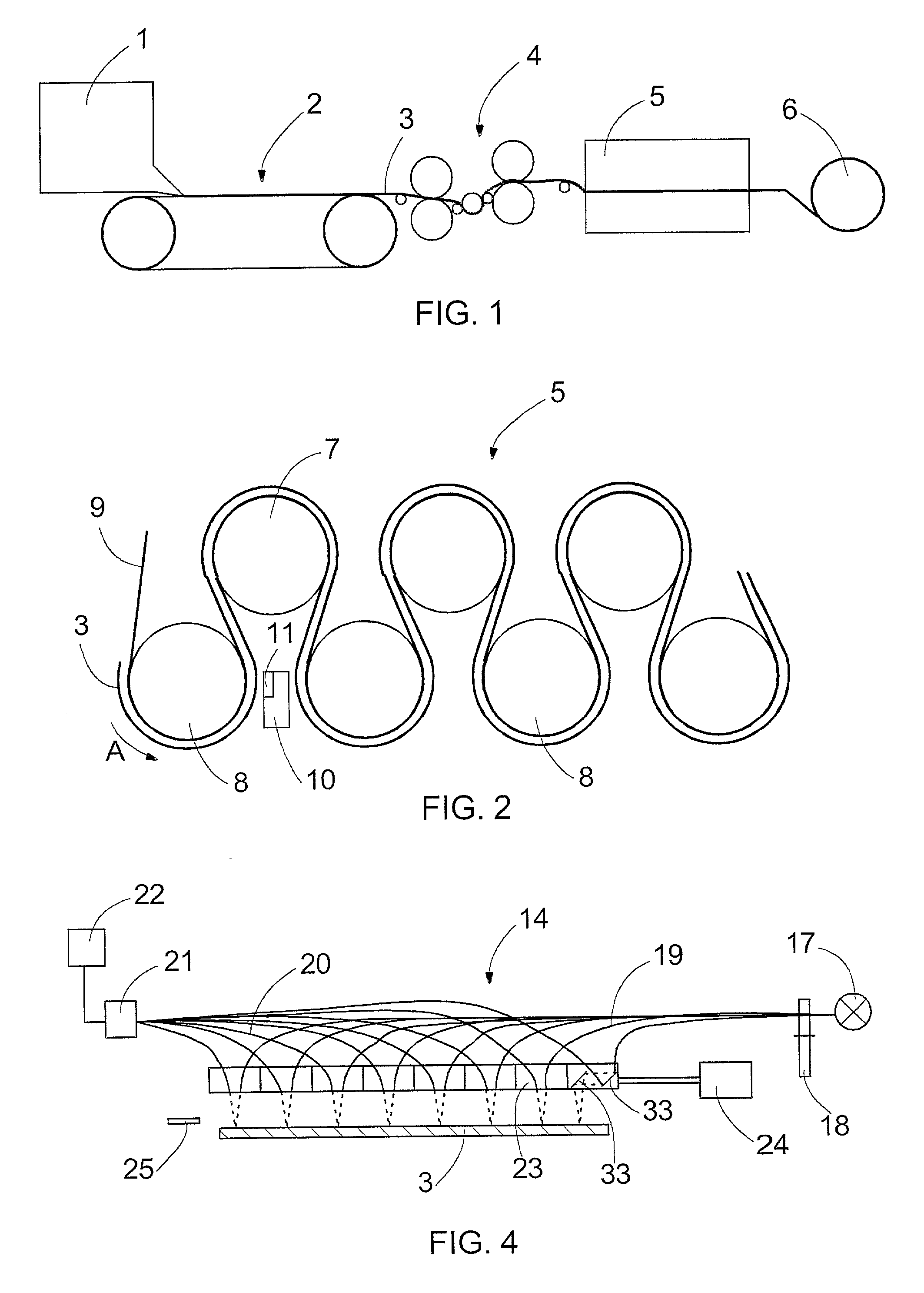
[0026]FIG. 1 schematically illustrates a paper machine. The paper machine comprises a head box 1, from which pulp is fed to a former 2, where a paper web 3 is formed from the pulp. The paper web 3 is guided to a press section 4 and further to a dryer unit 5. From the dryer unit 5 the web is guided to a reeler 6. The paper machine may also comprise other parts, e.g. a size press or a calender, which are not shown in FIG. 1 for the sake of clarity. The function of paper machine is also known per se to a person skilled in the art, for which reason it is not described more closely here.
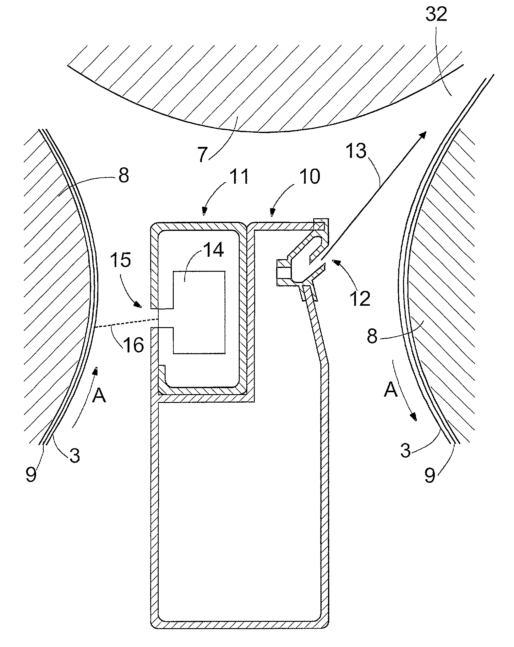
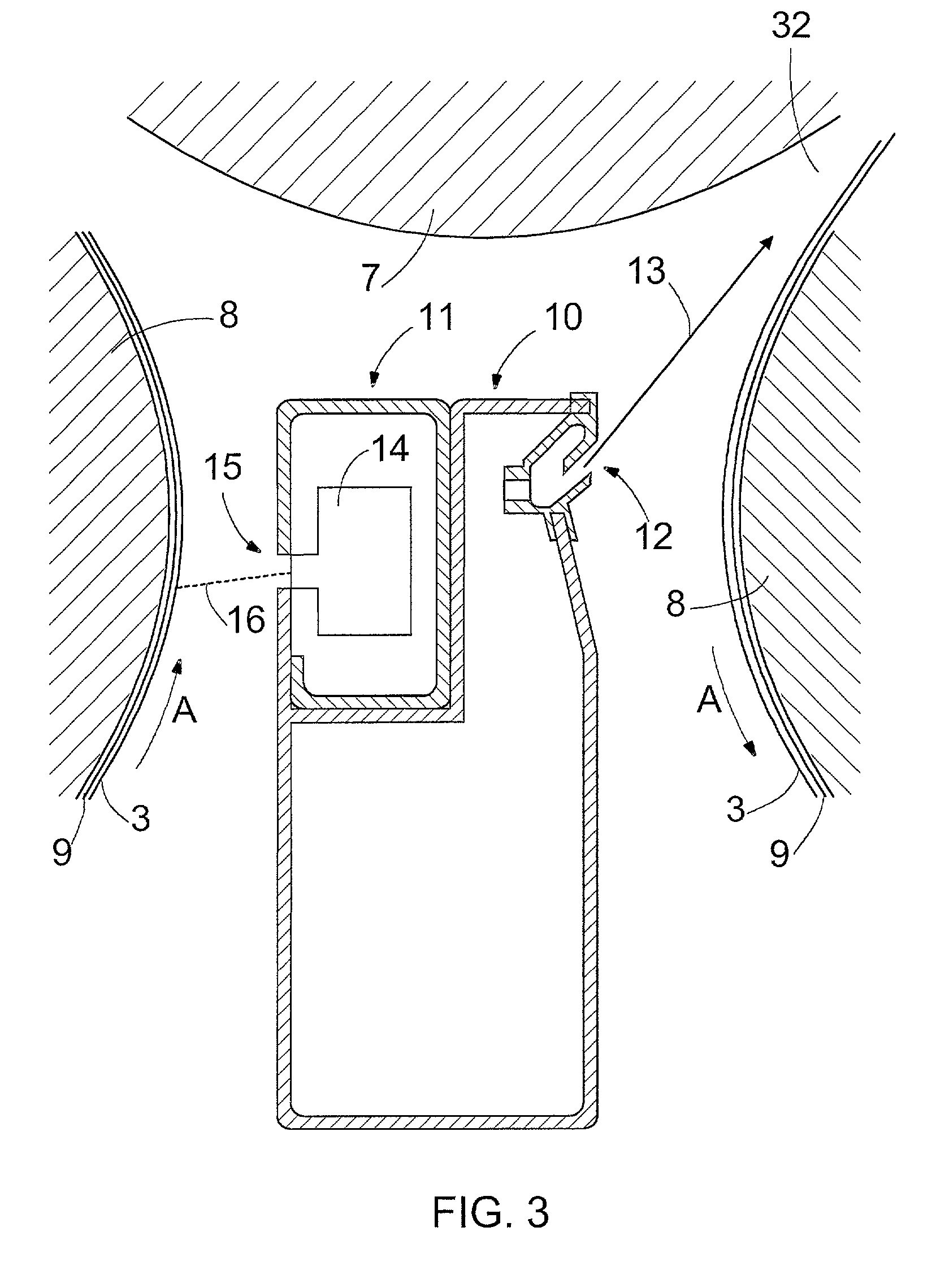
[0027]FIG. 2 schematically illustrates the forward end of the dryer unit 5 of the paper machine 1. FIG. 2 shows some of the drying cylinders included in the dryer unit 5, i.e. steam-heated rolls 7 in the upper part of the dryer unit 5, and vacuum rolls 8 in the lower part of the dryer unit 5. The rolls in the lower part of the dryer unit 5 do not need to be vacuum rolls but they may also be conventional c...
PUM
| Property | Measurement | Unit |
|---|---|---|
| Depth | aaaaa | aaaaa |
Abstract
Description
Claims
Application Information