Fluid oxygenator with access port

a technology of access port and oxygenator, which is applied in the direction of suction devices, medical devices, other medical devices, etc., can solve the problems of obstructing the actual flow of fluid through the device, affecting the oxygenation effect of fluid, and difficult removal of air bubbles, etc., to achieve the effect of facilitating fluid oxygenation

Inactive Publication Date: 2006-02-14
MEDTRONIC INC
View PDF18 Cites 20 Cited by
  • Summary
  • Abstract
  • Description
  • Claims
  • Application Information

AI Technical Summary

Benefits of technology

[0008]One aspect of the present invention provides a fluid oxygenating apparatus or oxygenator which includes a housing defining a chamber, a core within the chamber, the core including a channel, and a bubble release port communicating with the channel. This oxygenator may be arranged so that fluid may be flowed through the channel and bubbles may be released through the bubble release port. This bubble release port may be formed in a ca...

Problems solved by technology

Biocompatible coatings and the presence of blood in the device make removal of the air bubbles difficult, as they are unlikely to pass through the fiber wall or through the fiber bundle to the distal side.
These bubbles can cause a n...

Method used


Image

  • Fluid oxygenator with access port
  • Fluid oxygenator with access port
  • Fluid oxygenator with access port

Examples


second embodiment

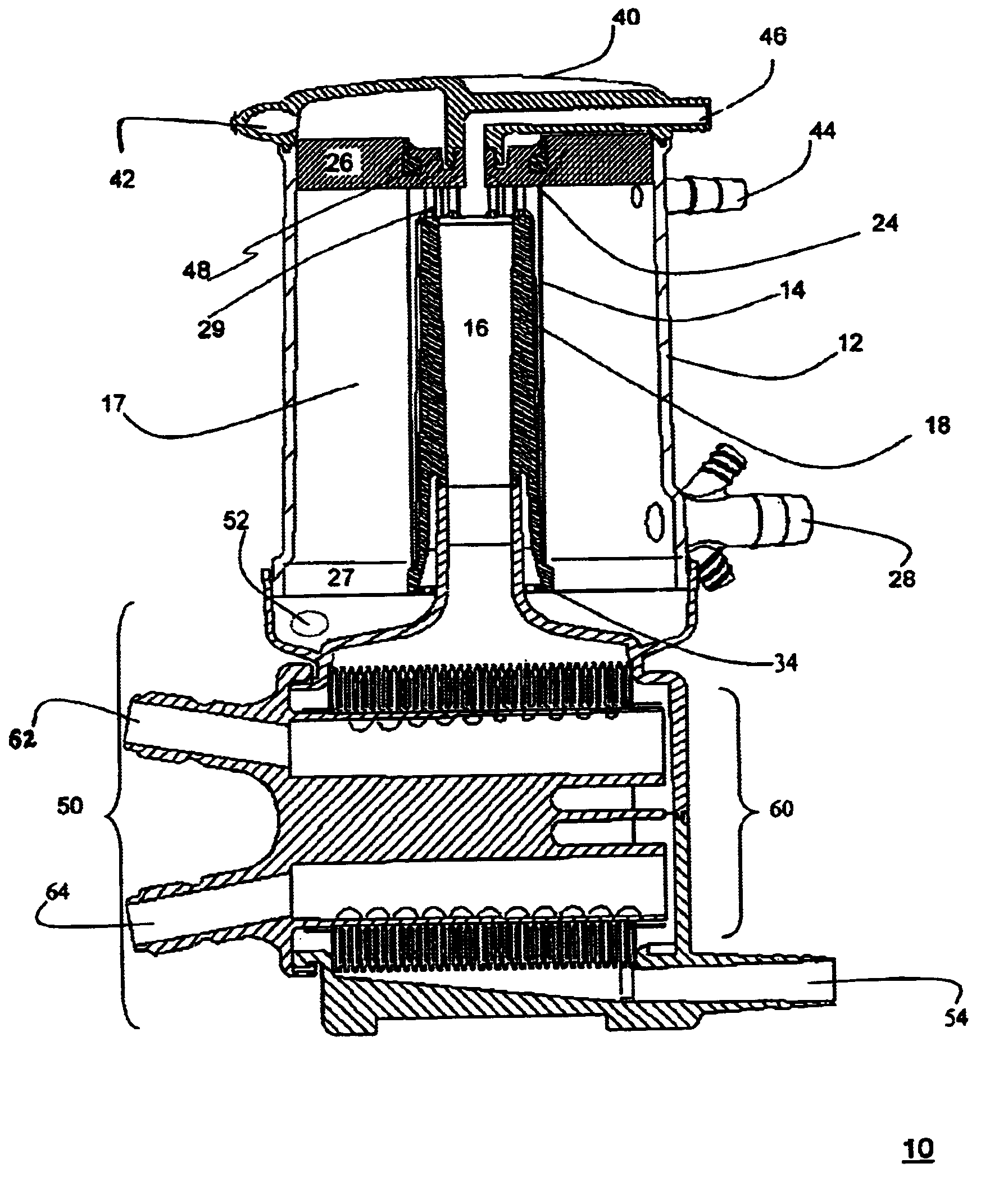
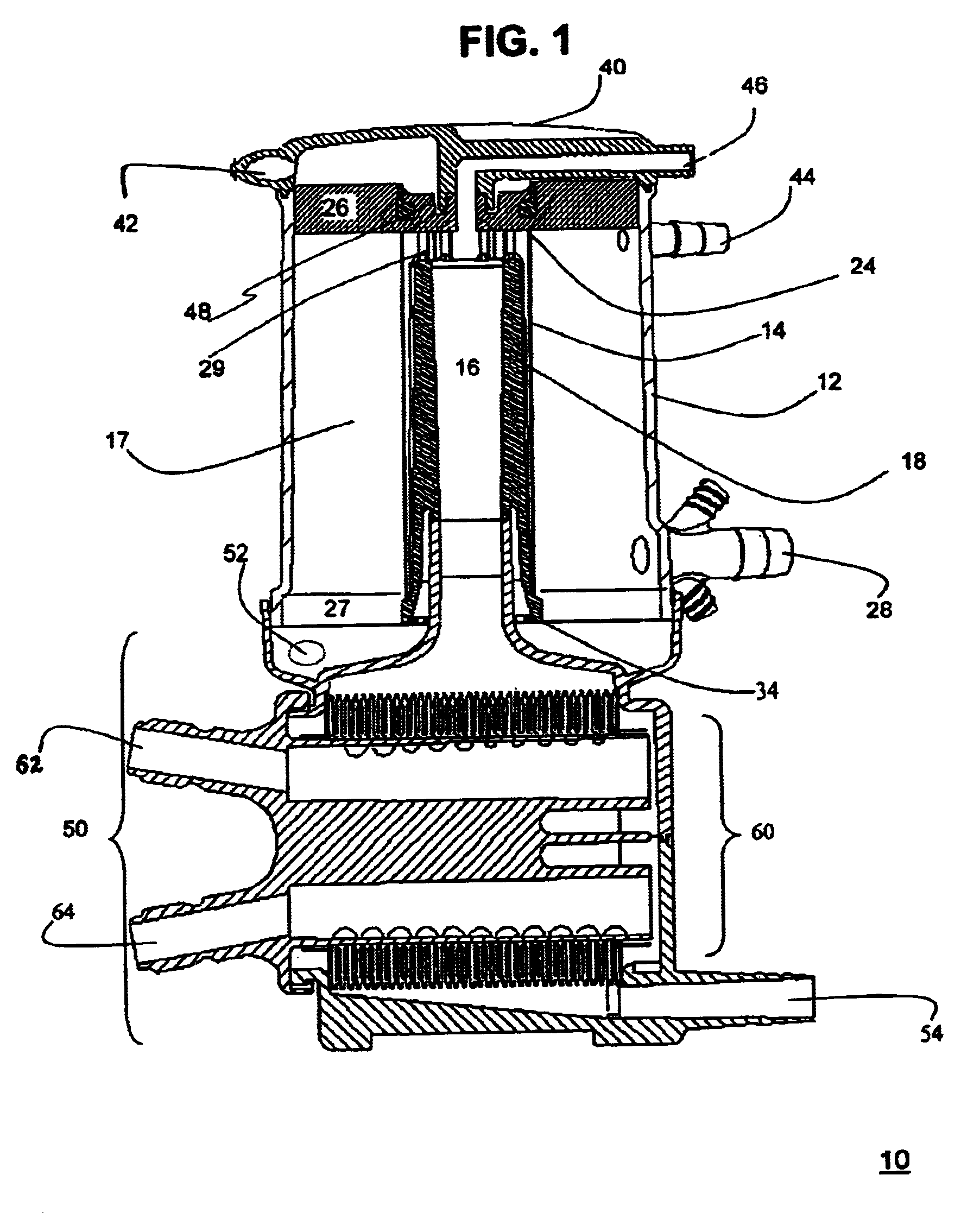
[0021]As shown in FIGS. 1 and 2, cap 40 also includes a bubble release port or access port 46. In one embodiment, access port 46 may be attached to the gas cap 40. In a second embodiment, the access port 46 is molded into gas cap 40. Alternatively, access port 46 may be a rigid or flexible tube or pathway that allows access to manifold 16 through the cap 40 or housing 12. When oxygenator 10 is in a typical vertical orientation, access port 46 allows access to the section of oxygenator 10 above potting means 26. Access port 46 may further allow access to the outer surface of core 14.

[0022]The gas cap 40 with access port 46 is mated to potting means 26, and thereby attached to oxygenator 10 as a whole, via mating feature 48.

[0023]Oxygenator 10 further includes a suitably located blood outlet 28. Outlet 28 may, as shown in FIG. 1 be located through housing 12 and adjacent the second end 34 of core 14.

[0024]The bottom of the oxygenator 10 is received in base 50. Base 50 includes gas out...

third embodiment

[0043]Referring to FIG. 5, access port 546 is shown. In this embodiment access port 546 is configured so that it has a substantially toroidal or helical configuration at one end 547. It is contemplated that access port 546 may also be configured so that the entire port has a substantially toroidal or helical configuration. In one embodiment, access port 546 may be attached to gas cap 540. In another embodiment, the port 546 is molded into gas cap 540. When the oxygenator is in a typical vertical orientation, access port 546 allows access to the section of the oxygenator above potting means 526. Access port 546 also allows access the manifold 516 within the core 514.

[0044]The gas cap 540 with attached port 546 is mated to potting means 526, and thereby attached to the oxygenator as a whole, via mating feature 548.

[0045]Debubbling occurs in the embodiment of FIG. 3 in a manner similar to that described above. The toroidal or helical shape may facilitate entrapment of the bubbles.


PUM


Abstract

A fluid oxygenating apparatus is provided which includes a housing defining a chamber, a core positioned within the chamber including a fluid channel formed therein, and a bubble release port communicating with the outlet end of the channel. Fluid is flowed through an inlet of the channel and bubbles are released through the bubble release port. A method and system for debubbling a fluid in such an apparatus is also provided.

Description

FIELD OF THE INVENTION[0001]This invention relates to devices that oxygenate and remove carbon dioxide from fluid, including blood. The invention further relates to devices that regulate the temperature of and debubble fluid as it passes through the device.BACKGROUND OF THE INVENTION[0002]Typical blood oxygenators may be used as artificial cardiorespiratory devices, for example, during cardiopulmonary bypass surgery. Such oxygenators serve as an artificial respiratory system for a patient at a time when the patient is unable to rely on his own respiratory system, e.g. during surgery. These devices act temporarily as a patient's heart and lungs, circulating, adding oxygen to and removing carbon dioxide from a patient's blood while the patient's own heart and lungs are inactive.[0003]It follows that a desirable oxygenator approximates as closely as possible the conditions and components of a patient's respiratory system. Forces mechanically applied to the blood as it flows through the...

Claims


Application Information

Patent Timeline
IPC IPC(8): A61M1/14A61M37/00A61M1/16
CPCA61M1/1698A61M1/1625Y10S261/28A61M1/3623
Inventor MCINTOSH, KEVIN D.JONES, BRUCE R.
Owner MEDTRONIC INC
Why Eureka
Try Eureka