Methods of operating a parallel hybrid vehicle having an internal combustion engine and a secondary power source

a hybrid vehicle and secondary power source technology, applied in the direction of engine-driven generators, machines/engines, electric generator control, etc., can solve the problems of delay in engine power use, and achieve the effect of reducing disruptions in the drivability of hybrid vehicles, quick supplemental torque to the vehicle, and increasing fuel savings

Inactive Publication Date: 2006-02-14
GOVERNMENT OF THE UNITED STATES OF AMERICA A
View PDF136 Cites 64 Cited by
  • Summary
  • Abstract
  • Description
  • Claims
  • Application Information

AI Technical Summary

Benefits of technology

[0011]In yet another embodiment, when certain operating conditions are deemed to exist, the ICE is turned off during the duration of a braking event, and subsequently restarted. By turning the engine off during the duration of the braking event, additional fuel savings may be obtained. And, by subsequently restarting the engine according to the existence of other various operating conditions, disruptions in the drivability of a hybrid vehicle may be minimized. The conditions required for engine “on” and engine “off” are discussed further below.
[0012]Additionally, regardless of which embodiment is employed, in instances where the vehicle is driven by the ICE alone, a second unit of energy stored within the energy storage device may be used to power the secondary power source and thereby provide quick supplemental torque to the vehicle. This method is used to propel the vehicle when large increases in further power output demand cause the vehicle to downshift, resulting in momentary disruptions of ICE power delivered to the wheels. By using the ICE and the secondary power source simultaneously, for brief periods of time, the degradation in drivability caused by such momentary disruptions in ICE power can be reduced or eliminated.

Problems solved by technology

However, when the first unit of energy is not above a selected level, the secondary power source is not used.
In such a scenario, although quicker transitions from the use of secondary power to ICE power may result, the use of engine power is still delayed, helping to achieve higher vehicle speeds before using the ICE.

Method used


Image

  • Methods of operating a parallel hybrid vehicle having an internal combustion engine and a secondary power source
  • Methods of operating a parallel hybrid vehicle having an internal combustion engine and a secondary power source
  • Methods of operating a parallel hybrid vehicle having an internal combustion engine and a secondary power source

Examples


Embodiment Construction

[0019]In the following description, certain specific details are set forth in order to provide a thorough understanding of various embodiments of the invention. However, one of ordinary skill in the art will understand that the invention may be practiced without these details. In other instances, well-known structures associated with hybrid vehicles have not been shown or described in detail to avoid unnecessarily obscuring descriptions of the embodiments of the invention.

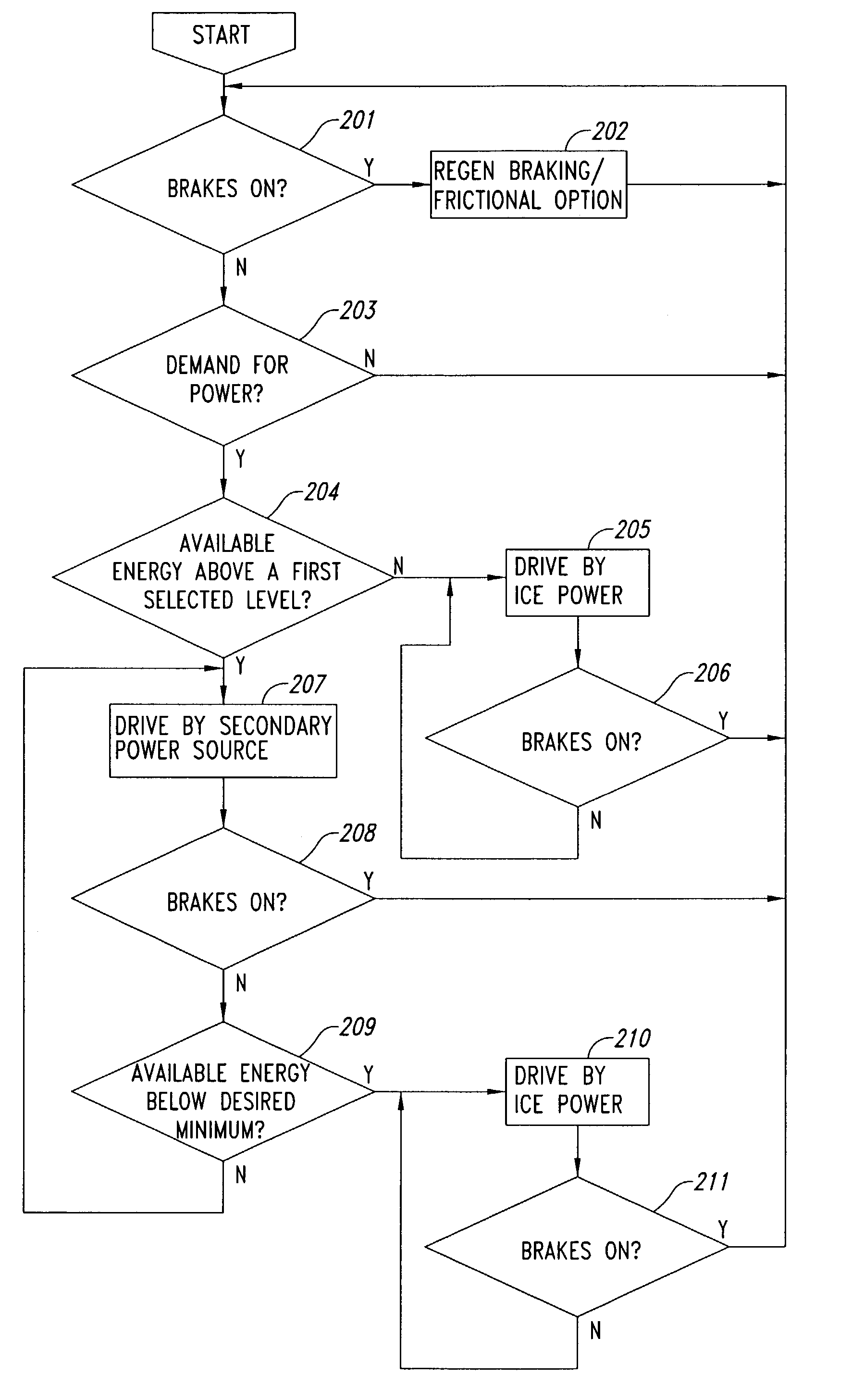
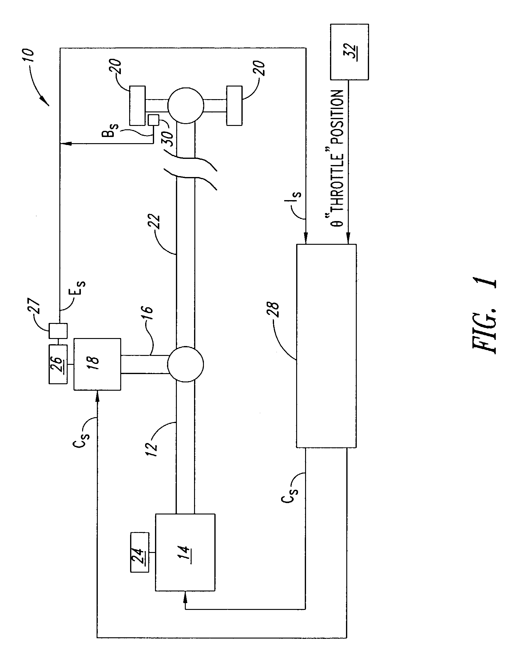
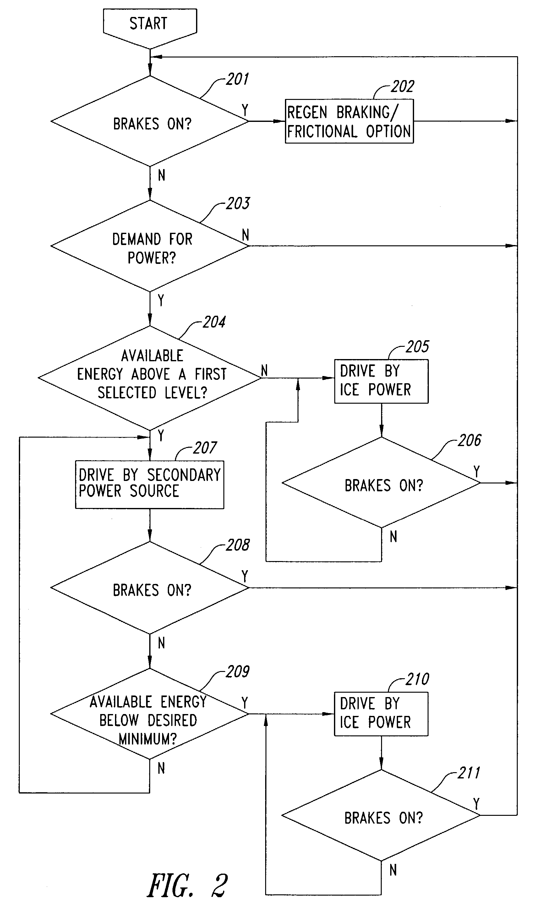
[0020]The term “secondary power source,” as used herein, denotes a non-ICE power source capable of using energy captured during the vehicle's braking process. Thus, a secondary power source may include, for example, one or more electric or hydraulic motors. As is to be understood by one of ordinary skill in the art, other like systems may also be employed, and the secondary motors described herein do not limit the scope of the invention.

[0021]The term “secondary,” as used herein, is arbitrarily assigned, and does n...


PUM


Abstract

The invention is directed toward methods for operating a parallel hybrid vehicle in a manner that responds to the operator's demand for power output, while maximizing engine efficiency and minimizing disruptions in vehicle drivability. According to principles of the present invention, when the driver of a hybrid vehicle makes a demand for power output immediately after a braking event, the power provided to meet the initial demand is from either an ICE or a secondary power source. Which power source is used, and when it is engaged and disengaged, depends on various vehicle operating conditions. Also, the ICE is selectively turned off and on in response to various operating conditions.

Description

BACKGROUND OF THE INVENTION[0001]1. Field of the Invention[0002]The present invention relates generally to methods for operating a hybrid vehicle and, more specifically, to methods for maximizing fuel efficiency while minimizing disruptions in drivability.[0003]2. Description of the Related Art[0004]Most vehicles employ conventional powertrain systems, which rely upon internal combustion engines (ICEs) as the sole source of power. Such systems are powered by fuel energy and, on average, achieve a thermal efficiency of 10–15%, while the remaining 85–90% of the fuel energy is wasted as heat. These heat losses are, in large part, due to the fact that ICEs can only produce energy and not reclaim it. Because conventional powertrain systems cannot recapture the vehicle's kinetic energy, frictional braking is used to slow or stop a vehicle, and in doing so, the vehicle's kinetic energy is converted to lost heat.[0005]Hybrid powertrain systems can mitigate the foregoing efficiency losses. A...

Claims


Application Information

Patent Timeline
Patent Type & Authority Patents(United States)
IPC IPC(8): B60L11/14E05C1/06E05C1/12F02N11/06H02P9/04B60K6/10B60K6/12B60K6/48B60L7/16B60L11/18B60L50/16B60T1/10B60W10/06B60W10/08B60W10/26B60W20/00
CPCB60K6/10B60K6/48B60L7/16B60L11/1851B60T1/10B60W10/06B60W10/08B60W10/26B60W20/00B60L11/14B60K6/12Y02T10/70B60W2510/0604B60W2510/244B60W2520/10B60W2720/106Y02T10/6208Y02T10/6221Y02T10/6282Y02T10/6286Y02T10/7005Y02T10/705B60L2240/12Y02T10/7077Y02T10/6204B60L50/16B60L58/10Y02T10/62Y02T10/7072B60W20/10
Inventor GRAY, JR., CHARLES L.
Owner GOVERNMENT OF THE UNITED STATES OF AMERICA A
Why Eureka
Try Eureka