Power system for supplying stable power

a power system and stable technology, applied in the direction of pulse technique, transportation and packaging, energy industry, etc., can solve the problems of less imbalanced component stress, less efficiency, and low efficiency of the conventional distributed system, so as to improve the efficiency and power density of the system, the effect of reducing the variation range of input voltage and prolonging the sustaining tim

Active Publication Date: 2006-02-14
LITE ON TECH CORP
View PDF4 Cites 29 Cited by
  • Summary
  • Abstract
  • Description
  • Claims
  • Application Information

AI Technical Summary

Benefits of technology

[0014]One object of the present invention is to provide a distributed power system, which can fully utilize the capacity of a storage capacitor of a PFC transformer to

Problems solved by technology

However, with this smaller duty ratio, the efficiency and power density of the conventional distributed system and the energy use efficiency of the storage capacitor of the PFC transformer 1a are relatively lower.
The smaller the duty ratio is, the more “asymmetric” the operating status of the transformer will be, leading to the more imbalanced component stress and the lower efficiency.
However, this will re

Method used


Image

  • Power system for supplying stable power
  • Power system for supplying stable power
  • Power system for supplying stable power

Examples


Embodiment Construction

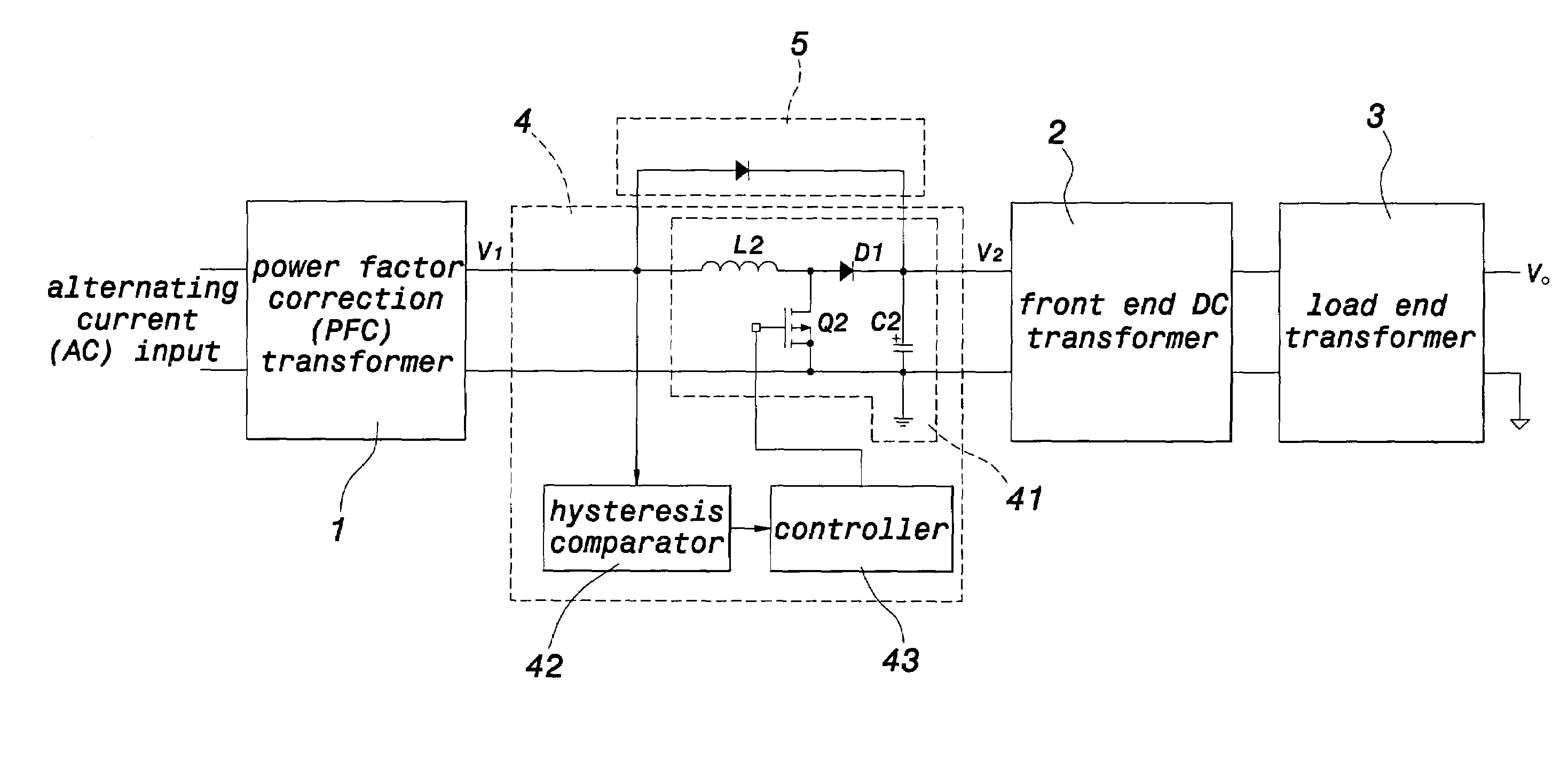
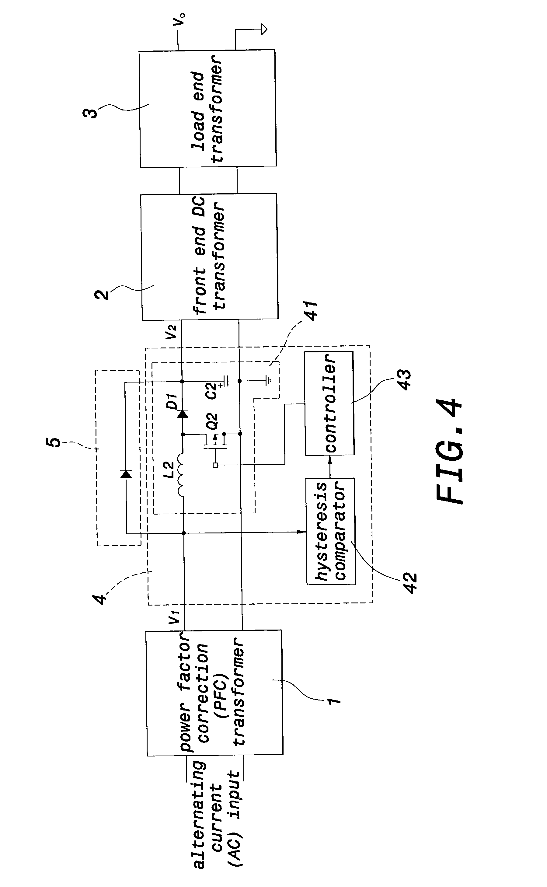
[0025]As shown in FIG. 4, the present invention provides a distributed power system, which can fully utilize the capacity of a storage capacitor of an PFC transformer to have a longer sustaining time and decrease the variation range of the input voltage of an FE DC transformer so as to improve the efficiency and power density thereof. In the distributed power system, a backup boost transformer 4 is connected between a PFC transformer 1 and an FE DC transformer 2 and is also parallel connected with a diode 5. The FE DC transformer 2 can be an AHB or another circuit topology. The backup boost transformer 4 sets a first preset voltage V.sub.2set to be lower than the normal output voltage V.sub.1set of the PFC transformer 1.

[0026]The backup boost transformer 4 includes a boost transformer topology 41, a hysteresis comparator 42, and a controller 43.

[0027]The boost transformer topology 41 includes a switching component Q2, an inductor L2, a diode D1, and a capacitor C2. The switching com...


PUM


Abstract

A distributed power system, wherein a backup boost transformer is connected between a PFC transformer and a FE DC transformer. The backup boost transformer is also parallel connected with a diode. The backup boost transformer only operates in the sustaining time, if the first DC voltage drops gradually, the backup boost transformer will increase this first DC voltage and stabilize it at a preset voltage of the FE DC transformer. Therefore, the capacity of the storage capacitor of the PFC transformer can be fully utilized to have a longer sustaining time and decrease the variation range of the second DC voltage so as to enhance the efficiency and power density thereof.

Description

BACKGROUND OF THE INVENTION[0001]1. Field of the Invention[0002]The present invention relates to a distributed power system and, more particularly, to a distributed power system used in a power transformer having a narrower normal direct current (DC) input range and keeping the output voltage thereof when the input voltage drops occasionally in a short time.[0003]2. Description of the Prior Art[0004]As shown in FIG. 1, a conventional distributed power system includes a power factor correction (PFC) transformer 1a, a front end (FE) DC transformer 2a, and a load end transformer 3a. The PFC transformer 1a is used to transform an alternating current (AC) input voltage into a high DC voltage (generally 400V), and performs the corresponding PFC in the input terminal thereof. The FE DC transformer 2a is used to transform the above high DC voltage into another DC voltage (generally 48V or 12V), and sends the DC voltage to the load end transformer 3a, which transforms the DC voltage into the...

Claims


Application Information

Patent Timeline
IPC IPC(8): H02J1/12H02M1/00H02M1/42
CPCH02M1/4266Y02B70/123Y02B70/10Y02P80/10
Inventor XING, YANSUN, XIAODONG
Owner LITE ON TECH CORP
Why Eureka
Try Eureka