
Electric motor with electronic brake

a technology of electric motors and electronic brakes, applied in the direction of dynamo-electric machines, electrical apparatus, field or armature current control, etc., can solve the problems of inability to braking, inability to braking, and inability to braking, so as to achieve the effect of convenient us

Inactive Publication Date: 2006-02-14
C & E FEIN GMBH & CO KG
View PDF23 Cites 13 Cited by
  • Summary
  • Abstract
  • Description
  • Claims
  • Application Information

AI Technical Summary

Benefits of technology

[0017]It is a sixth object of the invention to disclose a retarded electric series motor avoiding excess voltages resulting from fast switching electronic components.
[0047]In this way, a simple control is provided for controlling the intensity of braking.

Problems solved by technology

In addition, the utilization of a capacitor is seen as a disadvantage, since only one single capacitor discharge is possible, to initiate braking of the motor.
If this should not be sufficient to effect a reliable initiation of the braking mode, then also later no braking will be possible, once the capacitor is discharged.
However, the utilization of mechanical contactors for switching between an operating and a braking mode is considered a major disadvantage.
However, since the design utilizes fast switching electronic components high excess voltages may arise there from which may impair the reliability of the motor.

Method used


Image

  • Electric motor with electronic brake
  • Electric motor with electronic brake
  • Electric motor with electronic brake

Examples


Embodiment Construction

[0065]An electric motor according to the invention may be utilized, for instance, for driving a retarded or electronically braked angle power tool, such as for operating a retarded or electronically braked angle grinder, a saw or the like.

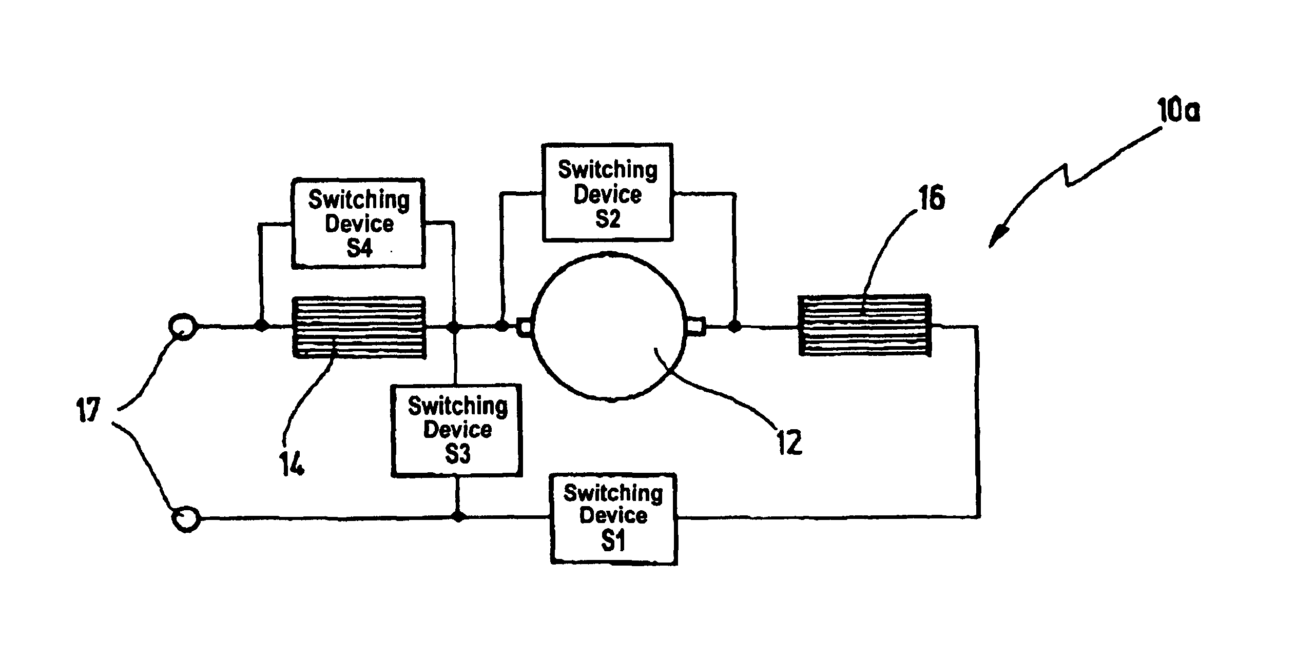
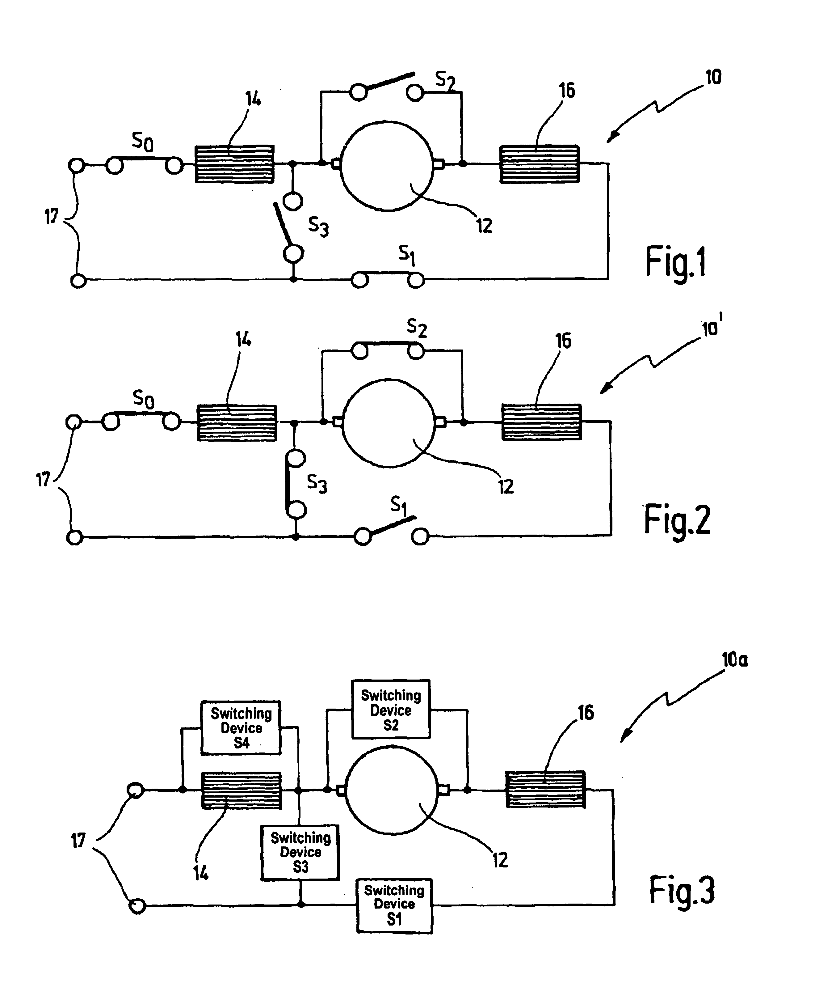
[0066]In the beginning, the basic principle of the invention shall be discussed with respect to a series motor according to the invention, shown in FIGS. 1, 2 and 3 in simplified manner.

[0067]While FIG. 1 depicts a series-wound motor 10 during operating mode, FIG. 2 depicts the series-wound motor 10′ during braking mode.

[0068]The series-wound motor 10 or 10′, respectively, comprises two field windings 14, 16 and an armature 12, which comprises an armature winding connected in a known manner via brushes that are depicted only schematically in FIGS. 1 and 2.

[0069]The armature 12 is connected between the two field windings 14, 16 in series and may be connected via a switch S1 (motor switch) with a supply voltage 17. In addition, a main switch S0 may b...


PUM


Abstract

A retarded electric motor designed as a series motor or an asynchronous motor having a squirrel cage rotor. A valve is provided for switching between motor operation and braking operation. During motor operation the motor is operated in a known configuration as series motor or as asynchronous motor. If configured as a series motor, the valve (S1, S2, S3) allows to bypass the armature and to operate the motor as an externally excited direct current generator when switching into braking operation. If configured as an asynchronous motor, a switch is utilized to disconnect at least two field windings from mains. A valve is utilized to excite the motor externally from mains with a pulsating direct current during braking.

Description

[0001]This application claims priority from pending German Patent Application No. 102 34 397.7 filed on Jul. 23, 2002.BACKGROUND OF THE INVENTION[0002]The invention relates to a retarded or electronically braked electric motor comprising at least one field winding and a commutating armature being connected in series with the at least one field winding and being fed during operating mode by a supply voltage, and further comprising means for switching into a braking mode.[0003]The invention further relates to an electric motor configured as an asynchronous motor comprising a squirrel cage rotor.[0004]A retarded or electronically braked electric motor as mentioned at the outset and designed as a series motor is known from WO 91 / 03866.[0005]Herein, for braking the series motor, a closed circuit disconnected from the power supply is formed via the field windings, commutating windings and the armature when switching from operating mode into braking mode. For limiting the braking current, ...

Claims


Application Information

Patent Timeline
Patent Type & Authority Patents(United States)
IPC IPC(8): H02P3/00H02P3/06
CPCH02P3/06
Inventor MEYER, CHRISTOPHKRESS, CHRISTOFSCHREIBER, ALFRED
Owner C & E FEIN GMBH & CO KG
Learn More