
Capacitive distance sensor

a capacitive distance and sensor technology, applied in the field of capacitive distance sensors, can solve the problems of discrimination, serious difficulty in detecting charges, and normalizing resulting data, and achieve the effect of preventing the unauthorized use of cellular phones

Inactive Publication Date: 2006-02-14
APPLE INC
View PDF65 Cites 37 Cited by
  • Summary
  • Abstract
  • Description
  • Claims
  • Application Information

AI Technical Summary

Benefits of technology

[0011]Fingerprint and other biometric sensors formed in accordance with the present invention will have application in preventing the unauthorized use of cellular phones, laptop computers, automobiles, automated teller machines, credit / debit card readers, POS terminals, and smart cards. They are also useful in authenticating electronic financial transactions, personal e-mail, providing access to buildings, etc. Biometric identification, such as personal identification and authentication alternatives which could be accomplished by mounting a sensor as taught by the present invention include hand or finger shape, facial shape, and facial features. In addition, the sensor device of the present invention could be used for non-biometric sensing, such as handwriting detection, switch actuation, and any other device requiring sensitivity to object proximity.

Problems solved by technology

In the above known capacitive sensor, the capacitance between the plates of a capacitor varies in inverse proportion to the distance between the plates, which therefore poses the problem of normalizing the resulting data.
In particular, if the capacitance being measured is very small, as in the application in question, serious difficulty is encountered in detecting the charge and discriminating between the various intermediate charge levels corresponding to different gray levels of the image to be generated in the presence of a low signal / noise ratio.

Method used


Image

  • Capacitive distance sensor
  • Capacitive distance sensor
  • Capacitive distance sensor

Examples


Embodiment Construction

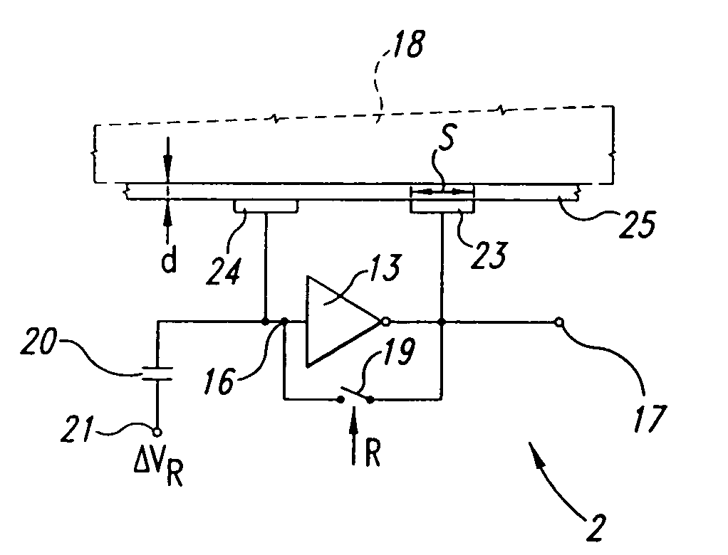
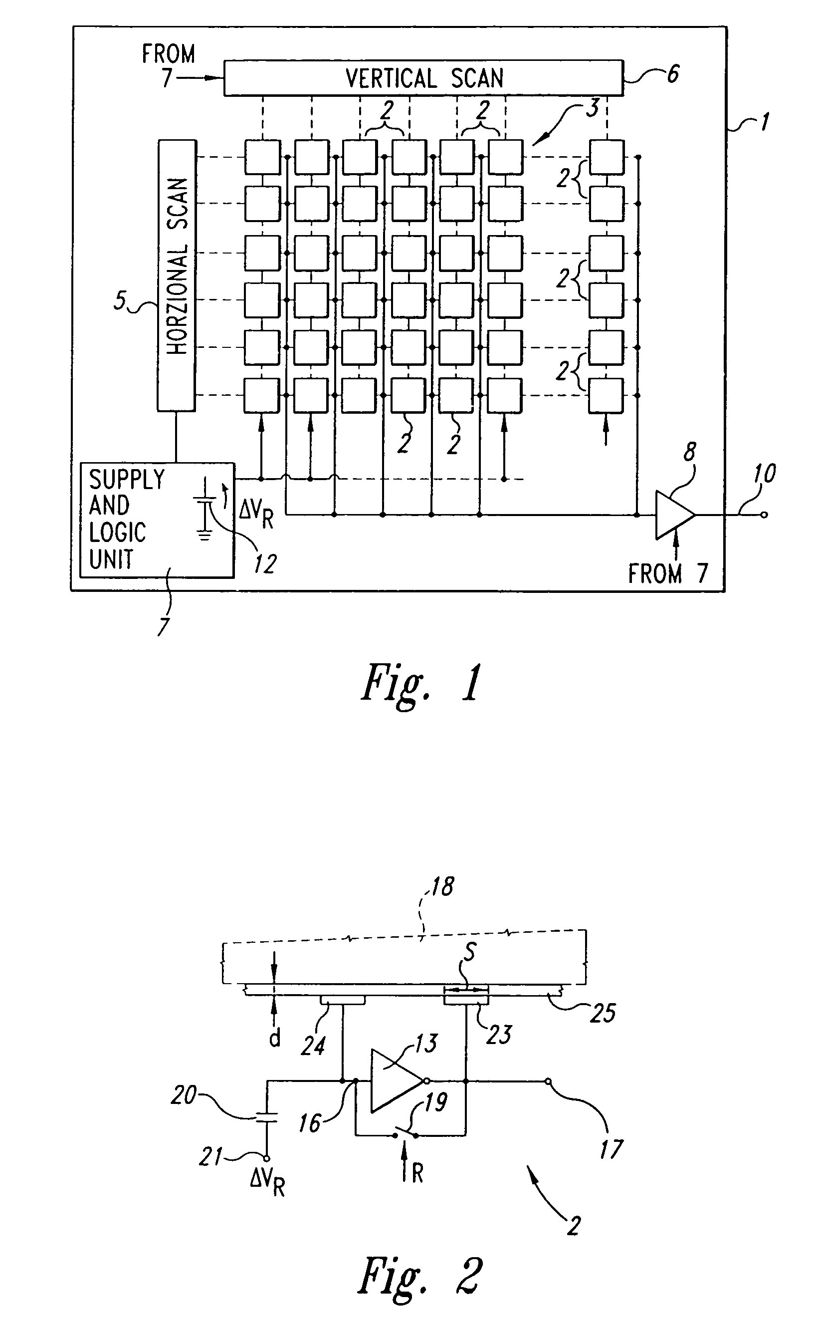
[0019]FIG. 1 shows a sensor device 1, preferably embodied in an integrated chip, comprising a number of cells 2 arranged to form an array 3 and each constituting an elementary sensor. The simplicity of the individual cells 2 enables the sensor device 1 to be implemented in integrated from on a single semiconductor chip.

[0020]The sensor device 1 also comprises a horizontal scanning stage 5 and a vertical scanning stage 6 for enabling one of the cells 2 at a time according to a predetermined scanning pattern. Preferably, to read the cells, stages 5, 6 enable the outputs of the cells 2 sequentially, and comprise shift registers. Alternatively, other cell reading devices could be employed, such as a random access decoder that reads addressed cells rather than sequentially scanning the cells 2.

[0021]The sensor device 1 also comprises a supply and logic stage 7, which supplies the components of the device with power (including the cells 2), feeds the necessary reference voltages, and cont...


PUM


Abstract

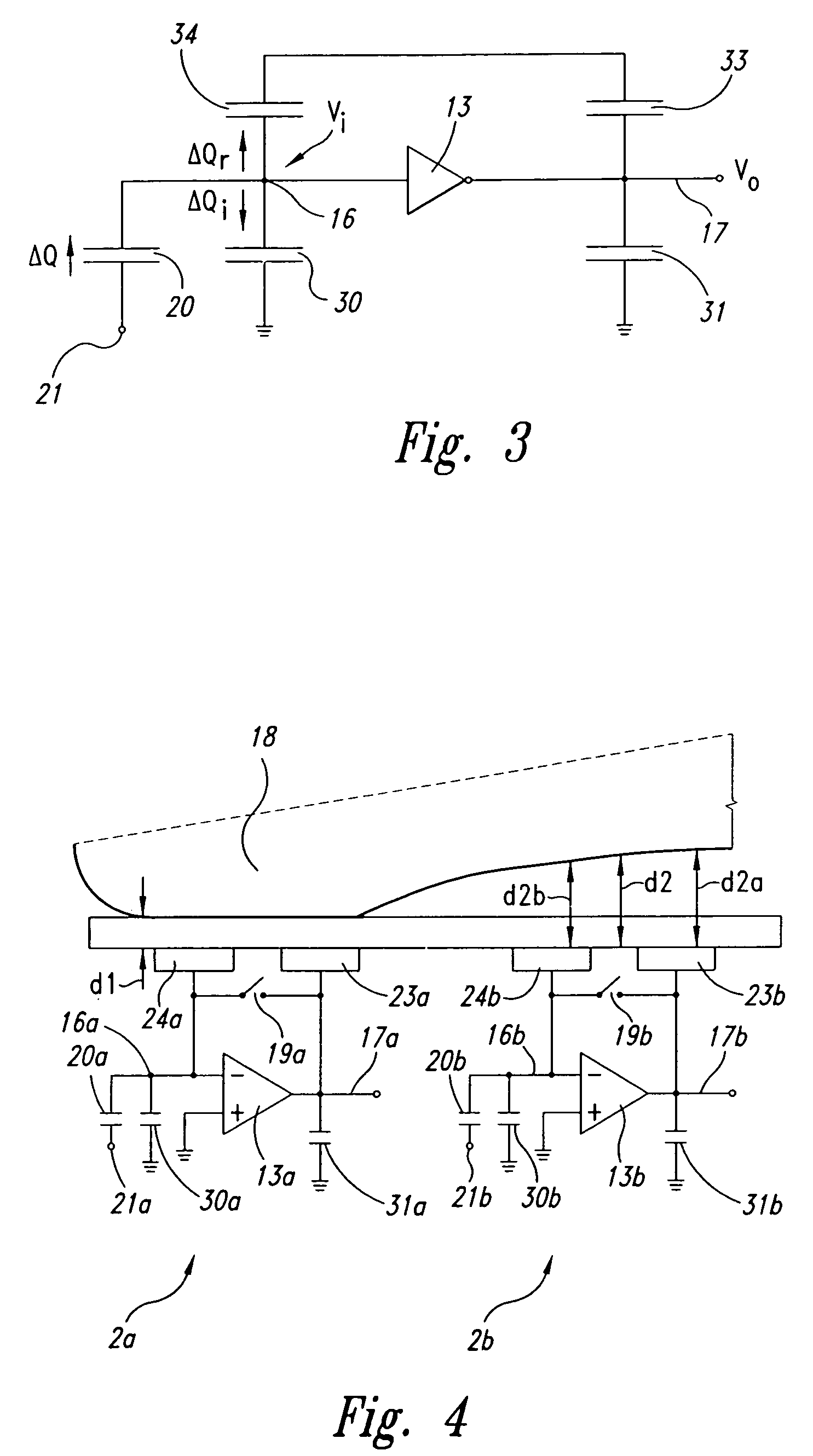
A distance sensor has a capacitive element in turn having a first plate which is positioned facing a second plate whose distance is to be measured. In the case of fingerprinting, the second plate is defined directly by the skin surface of the finger being printed. The sensor includes an inverting amplifier, between the input and output of which the capacitive element is connected to form a negative feedback branch. By supplying an electric charge step to the input of the inverting amplifier, a voltage step directly proportional to the distance being measured is obtained at the output.

Description

CROSS-REFERENCE TO RELATED APPLICATION[0001]This application is a division of U.S. patent application Ser. No. 09 / 999,065 filed Oct. 30, 2001 now U.S. Pat. No. 6,731,120, entitled “Capacitive Distance Sensor.” which is a division of Ser. No. 09 / 019,496 filed Feb. 5, 1998, now U.S. Pat. No. 6,320,394, which is a continuation-in-part of U.S. patent application Ser. No. 08 / 799,548, filed Feb. 13, 1997, now abandoned.TECHNICAL FIELD[0002]The present invention relates to a capacitive distance sensor, in particular, a small-distance (micrometric to millimetric) sensor.BACKGROUND OF THE INVENTION[0003]Small-distance sensors are used, among other things, as pressure, proximity, roughness, mechanical stress and acceleration sensors, for example, in integrated microphony and for acquiring fingerprints.[0004]For fingerprint acquisition in particular (to which reference is made herein purely by way of example of a preferred application of the present invention), known sensors include various ty...

Claims


Application Information

Patent Timeline
Patent Type & Authority Patents(United States)
IPC IPC(8): G01R27/26G01B7/004G01B7/02G01B7/34G06K9/00
CPCG01B7/004G06K9/0002G01B7/34G01B7/023G06V40/1306
Inventor TARTAGNI, MARCO
Owner APPLE INC
Learn More