Communication resource management method and node control device using priority control and admission control

Inactive Publication Date: 2006-02-14
IBM CORP
View PDF10 Cites 168 Cited by
  • Summary
  • Abstract
  • Description
  • Claims
  • Application Information

AI Technical Summary

Benefits of technology

[0026]It is therefore an object of the present invention to provide a communication resource management method and a node device which are capable of resolving the above noted second and third problems, without requiring the core nodes inside the network to carry out a processing with respect to packets that accounts for their flows, that is, while resolving the above noted first problem.
[0032]In this aspect, each node inside the network can manage the resources to be consumed at the own node, so that it becomes easier to conjecture a transfer capability required for the own node according to a change in time of the resources to be consumed, and thereby it becomes easier to make a node capability augmentation plan.
[0033]In addition, it is possible to carry out the management of the resources to be consumed for each set of flows, so that it is possible to reduce the processing load compared with the case where only the management for each flow is possible.
[0034]Note that, by managing the resources to be consumed at the own node, it becomes possible to obtain the remaining resources from the resources to be consumed and the transfer capability of the own node, and by notifying the remaining resources to the edge node, it becomes possible for the edge node to make a judgement as to whether or not to accept a new resource allocation request.

Problems solved by technology

Also, the attention is paid to the fact that the above noted third problem is caused because each node inside the network has no way of knowing the reserved bandwidth of the flow that passes through the own node.

Method used


Image

  • Communication resource management method and node control device using priority control and admission control
  • Communication resource management method and node control device using priority control and admission control
  • Communication resource management method and node control device using priority control and admission control

Examples


first embodiment

[0075]Referring now to FIG. 4 to FIG. 6, a communication resource management method and a node device according to the present invention will be described in detail.

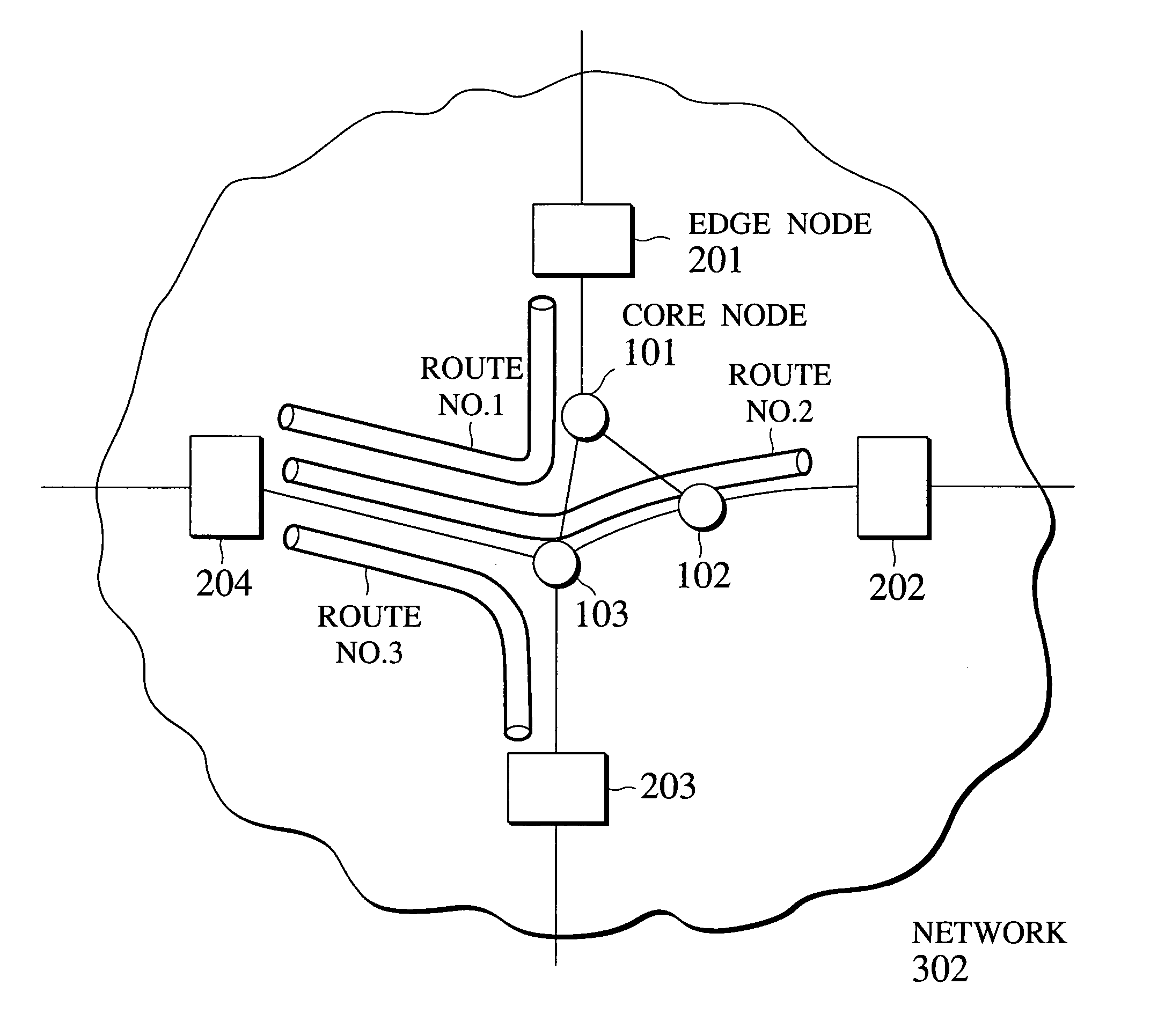
[0076]FIG. 4 shows an exemplary case of the packet transfer in a network 302 according to this first embodiment, where the edge node (204 for example) has a setting for a maximum value of an amount up to which the high priority tags can be attached for each route inside the network, and carries out the bandwidth reservation request admission control such that the amount for which the high priority tags are actually attached will not exceed that setting value. This setting value should preferably be set such that the communication quality (e.g., packet loss ratio, delay) for packets to which the high priority tags are attached will be at a certain level even when all the edge nodes attach the high priority tags fully up to the respective setting values, by accounting for the transfer capability of each node inside the net...

second embodiment

[0086]Referring now to FIG. 7 to FIG. 14, a communication resource management method and a node device according to the present invention will be described in detail.

[0087]In this second embodiment, each edge node notifies the reserved bandwidth to each node inside the network by using a reserved bandwidth notification packet, such that each node inside the network can ascertain a value of the reserved bandwidth of a flow that passes through the own node, that is, a value of the bandwidth to be consumed at the own node, according to the reserved bandwidth notification packet. In this way, it becomes easier to realize the network management such as making of a node transfer capability augmentation plan.

[0088]FIG. 7 shows an exemplary format of the reserved bandwidth notification packet. Here, the reserved bandwidth notification packet is to be transmitted as an IP packet, and comprises an IP header, a flow group identifier field, an allocated bandwidth field, and a source node field....

third embodiment

[0123]Referring now to FIG. 15 to FIG. 18, a communication resource management method and a node device according to the present invention will be described in detail.

[0124]In this third embodiment, the node inside the network notifies the edge node about the remaining bandwidth calculated from the reserved bandwidth management table as described in the second embodiment and the communication resources of the own node, such that upon receiving a new bandwidth reservation request the edge node can carry out the admission control (for admitting the request in the case where a certain communication quality can be provided inside the network) with respect to the received bandwidth reservation request. Note in particular that this has been realized in the first embodiment by statically setting the maximum value of the bandwidth that can be reserved for each route, whereas this third embodiment enables the edge node to carry out the admission control dynamically according to the bandwidth...


PUM


Abstract

A communication resource management scheme capable of guaranteeing the communication quality with respect to the flow while not requiring the processing for each flow to nodes other than edge nodes is disclosed. The edge node stores an information for obtaining an available amount of communication resources that can be newly allocated in the network to one set of flows which share at least a route from that edge node to an egress node of the network. Then, the edge node carries out an admission control by newly receiving a request for allocation of communication resources for one flow belonging to that one set of flows, judging whether or not to accept the request according to a requested amount of communication resources and the available amount of communication resources as obtained from the information stored for that one set of flows, and allocating requested communication resources to that one flow when it is judged that the request is to be accepted, while the edge node and the core node carry out the priority control.

Description

[0001]This application is a continuation of 09 / 176,794 filed Oct. 22, 1998 now U.S. Pat. No. 6.643.258.BACKGROUND OF THE INVENTION[0002]1. Field of the Invention[0003]The present invention relates to a communication resource management method and a node device for the purpose of providing a certain level of communication quality in a packet communication network.[0004]2. Description of the Background Art[0005]In the IP (Internet Protocol) network, for instance, an amount of delay caused for packets will be larger when the number of packets that arrive at a router for carrying out packet transfer becomes larger. In this case, however, each terminal is responsible for making a judgement as to whether or not to reduce a load of the router by limiting the number of packets to be transmitted from the terminal, and the terminal has no obligation to limit the number of packets to be transmitted.[0006]This is due to the fact that the Internet Protocol is designed without any consideration f...

Claims


Application Information

Patent Timeline
Patent Type & Authority Patents(United States)
IPC IPC(8): H04L12/56G06F13/00H04L12/46H04L12/70
CPCH04L12/5695H04L47/10H04L47/2433H04L47/2441H04L47/826H04L47/33H04L47/724H04L47/805H04L47/822H04L47/31H04L47/70
Inventor ISE, KATAROSHIMOJO, YOSHIMITSUKATSUBE, YASUHIRO
Owner IBM CORP
Why Eureka
Try Eureka