Technique for emulating differential signaling

a technology of differential signaling and signal pin count, applied in the field of signal transmission techniques, can solve the problems of differential signaling being prohibitive in terms of signal pin count, packaging size, cost, etc., and achieve the effect of improving recovery

Inactive Publication Date: 2006-02-14
RAMBUS INC
View PDF4 Cites 147 Cited by
  • Summary
  • Abstract
  • Description
  • Claims
  • Application Information

AI Technical Summary

Benefits of technology

[0010]In still another exemplary embodiment of the present invention, the technique is realized as an improved method for recovering a plurality of encoded signals, wherein the plurality of encoded signals have a spatial run length of at least two, and wherein each particular one of the plurality of encoded signals has at least two neighboring others of the plurality of encoded signals such that at least one of the at least two neighboring others of the plurality of encoded signal

Problems solved by technology

This increased signal pin count needed for differential signaling becomes an issue with integrated circuits (IC's) that have a very wide input/output (I/O) interfa

Method used


Image

  • Technique for emulating differential signaling
  • Technique for emulating differential signaling
  • Technique for emulating differential signaling

Examples


Embodiment Construction

)

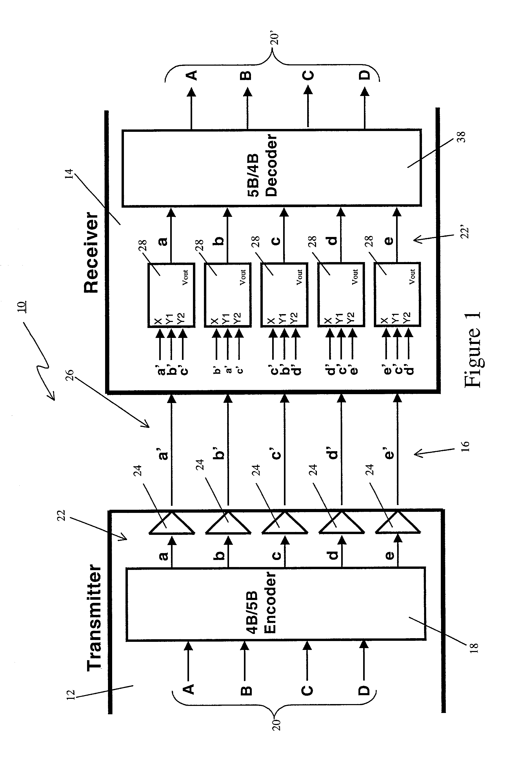
[0025]Referring to FIG. 1, there is shown a system 10 for emulating differential signaling in accordance with the present invention. The system 10 emulates differential signaling in accordance with the present invention by obtaining at least some of the above-described advantages of differential signaling without actually generating traditional differential signals and thereby realizing the above-described disadvantages associated with differential signaling. The system 10 comprises a transmitter 12 and a receiver 14 interconnected by a plurality of electrically conductive signal paths 16.

[0026]At this point it should be noted that the system 10 may be encompassed within a single integrated circuit, or formed with several integrated or discrete circuits. For example, the transmitter 12 and the receiver 14 could each be an integrated circuit, and the plurality of electrically conductive signal paths 16 could be a plurality of transmission lines. More particularly, the transmitter 12...


PUM


Abstract

A technique for emulating differential signaling is disclosed. In one exemplary embodiment, the technique is realized by encoding a plurality of input signals so as to generate a plurality of encoded signals having a spatial run length of N, wherein N is an integer having a value of at least two. Each of the plurality of encoded signals is then transmitted over a transmission medium so as to provide a respective plurality of transmitted encoded signals. Each of the plurality of transmitted encoded signals is then compared with at least N neighboring others of the plurality of transmitted encoded signals so as to recover a representation of each of the plurality of encoded signals. Each of the plurality of recovered encoded signals is then decoded so as to generate a plurality of decoded signals representing the plurality of input signals.

Description

FIELD OF THE INVENTION[0001]The present invention relates generally to signal transmission techniques and, more particularly, to a technique for emulating differential signaling.BACKGROUND OF THE INVENTION[0002]Differential signaling has many advantages over single ended signaling: smaller signal swing, increased noise immunity, constant output drive current (i.e., di / dt=0 for output drive circuitry), and pattern independent propagation delay (i.e., tpd not pattern dependent). However, differential signaling requires a larger number of signal pins (˜1.5× to 2×) than single ended signaling. This increased signal pin count needed for differential signaling becomes an issue with integrated circuits (IC's) that have a very wide input / output (I / O) interface. For example, memory controllers that have a 128-bit wide data interface to memory devices may require an additional 128 signal pins to implement full differential signaling. Thus, for IC's with a large number of data / address signal p...

Claims


Application Information

Patent Timeline
IPC IPC(8): H04B14/06H03M5/00
CPCH04L25/4908H04L25/0272
Inventor RAJAN, SURESH
Owner RAMBUS INC
Why Eureka
Try Eureka