Time and frequency windowed pocket cardiac stethoscope

a pocket cardiac stethoscope and time and frequency window technology, applied in the field of stethoscopes, can solve the problems of failure to trigger at all, physical large device without timing reference indicator or visible display, and inability to provide frequency response processing or control, etc., to achieve the effect of being easily heard and identified

Inactive Publication Date: 2006-02-14
CHELEN WILLIAM E
View PDF17 Cites 8 Cited by
  • Summary
  • Abstract
  • Description
  • Claims
  • Application Information

AI Technical Summary

Benefits of technology

[0009]The present invention obviates the need for much of the slowly acquired auscultatory skills referred to above by permitting the electronic selection of portions of the cardiac cycle to be amplified and tuned, and, subsequently, to be much more easily heard and identified. The invention also provides automatic compensation for cardiac size (by providing an automatic gain control to precisely determine triggering of each new cardiac cycle), and, potentially, the automatic determination of cardiac cycle length to further automate the auscultation process.

Problems solved by technology

The device suffers from potential false triggering of the time-filtering interval by the T-wave of the electrocardiogram or, potentially, a failure to trigger at all in an individual with low amplitude body surface potentials.
This physically large device has no timing reference indicator or visible display and does not provide any frequency response processing or control.
The device also requires numerous manual controls that can easily be mis-set and thus obviate correct functional control of the time-filtering in individuals with cardiac cycles of unusual length.
In spite of the above, the art of stethoscopy remains a challenging one in large part due to the great effort and time required to acquire the concentration and mental time windowing necessary to isolate and identify sometimes very brief and low amplitude physiologic sounds.

Method used


Image

  • Time and frequency windowed pocket cardiac stethoscope
  • Time and frequency windowed pocket cardiac stethoscope
  • Time and frequency windowed pocket cardiac stethoscope

Examples


Embodiment Construction

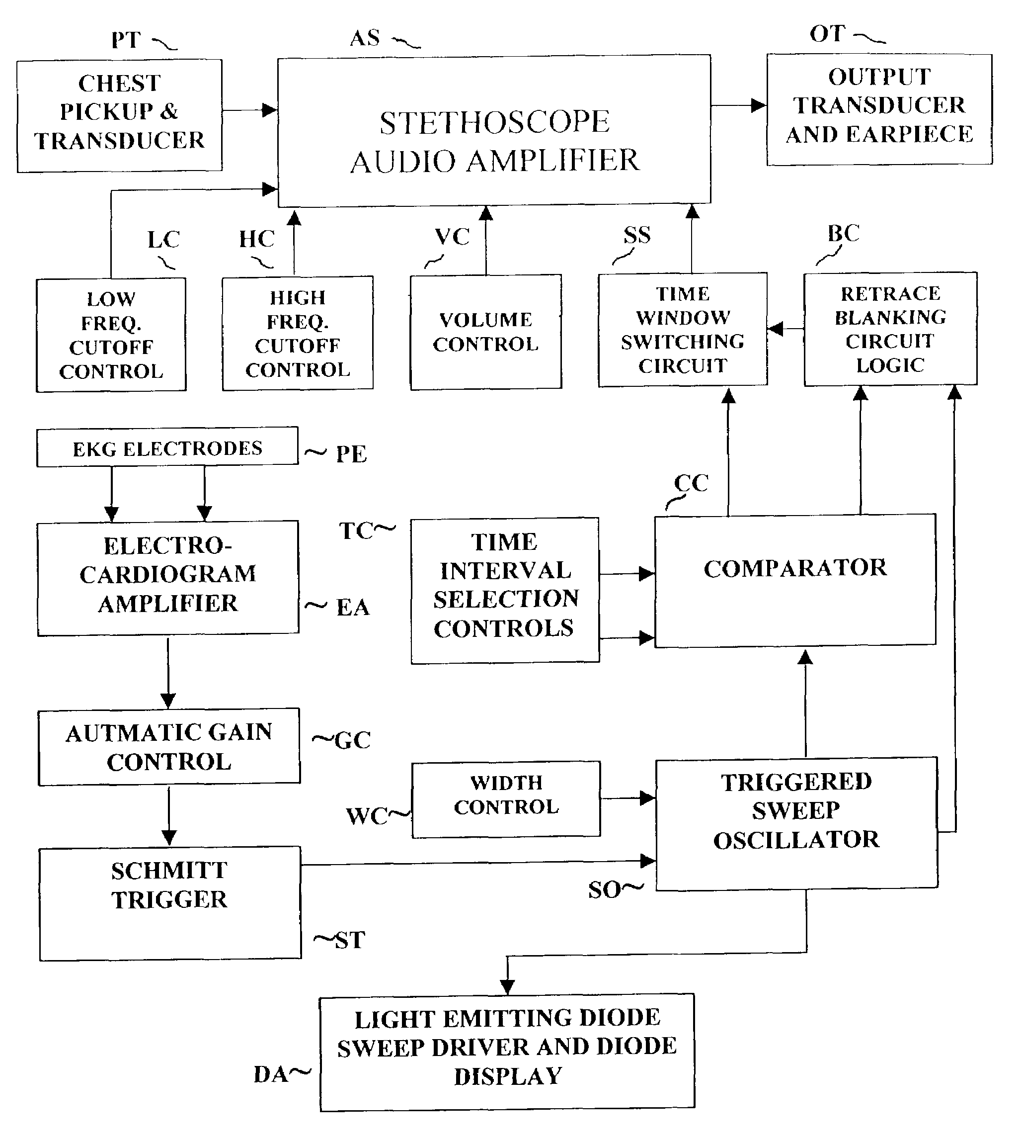
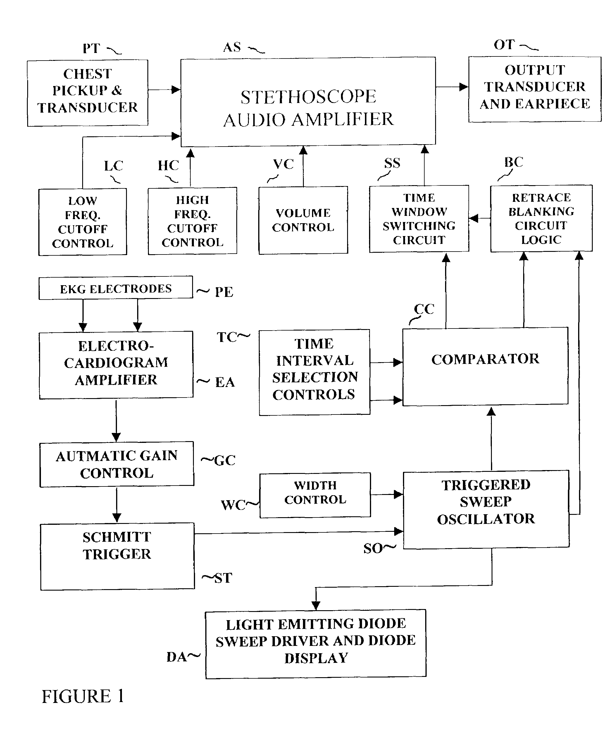
[0017]In the preferred embodiment of the invention shown in FIG. 1, the device or system includes an amplified electronic frequency-band selective stethoscope AS, and an electrocardiogram amplifier EA. The latter is connected through an electrocardiogram automatic gain control circuit GC, and a Schmitt trigger ST, to a sawtooth ramp / sweep oscillator SO. The output of sweep oscillator SO form one input to a variable / adjustable comparator circuit CC as well as an input to a light emitting diode (LED) driver and display array DA and to a “retrace” noise suppression (blanking) circuit BC. Comparator CC provides inputs an electronic time-window switching system or circuit SS and to blanking circuit BC.

[0018]The device of FIG. 1 also includes a chest pickup and transducer PT and an output transducer and earpiece OT. A low frequency cutoff control circuit LC, a high frequency cutoff control circuit HC, and a volume control circuit VC form inputs to stethoscope AS while skin surface EKG pic...


PUM


Abstract

A temporally and frequency controlled amplified cardiac stethoscope device is provided wherein frequency response selection is carried out by manually tuning two active filters thereby permitting user pass band (high and low frequency cutoff) selection. Simultaneously, the user is able to select a time window, or interval, of the audio output of the device for specific aural observation, to the exclusion of the remainder of cardiac cycle sounds. The device is miniaturized to permit transport in a clothing pocket and use in the clinic or at the bedside. The device is based upon electrocardiographic QRS complex/electronic Schmitt trigger synchronization of a sweep generator and comparator. The synchronization signal, in combination with manual user inputs, permits the control of digital/analog switching of on/off time intervals of a variable frequency response electronic stethoscope.

Description

FIELD OF THE INVENTION[0001]The present invention generally relates to stethoscopes and, more particularly, to an improved electronic cardiac stethoscope.RELATED ART[0002]The stethoscope has undergone many varieties of modification since its invention in 1819. These modifications have typically been attempts to increase the ability to detect and interpret the frequently subtle physiologic sounds originating in the thorax. Most of these modifications have occurred since the availability of small electronic components.[0003]Numerous electronic stethoscopes have been proposed or developed over the past several decades. The predominant concept embodied by the majority of them has been one of controlled and variable amplification of physiologic sounds, e.g., U.S. Pat. No. 4,618,986, U.S. Pat. No. 4,170,717 and U.S. Pat. No. 4,438,772. Another concept in stethoscope improvement has been the effort in noise reduction or modification, e.g., U.S. Pat. No. 5,602,924 and U.S. Pat. No. 5,610,98...

Claims


Application Information

Patent Timeline
Patent Type & Authority Patents(United States)
IPC IPC(8): A61B7/04H03G3/30H03G5/10
CPCA61B7/04H03G5/10H03G3/301A61B5/318
Inventor CHELEN, WILLIAM E.
Owner CHELEN WILLIAM E
Why Eureka
Try Eureka