Method of forming image and image forming apparatus

a technology of image and forming apparatus, applied in the field of forming image and image forming apparatus, can solve the problems of inability to improve the linearity of gradation -characteristics, difficult to increase the density of a highlight, and difficult to achieve both. , to achieve the effect of high densities

Inactive Publication Date: 2006-02-14
SEIKO EPSON CORP
View PDF3 Cites 6 Cited by
  • Summary
  • Abstract
  • Description
  • Claims
  • Application Information

AI Technical Summary

Benefits of technology

[0008]The invention solves the above-described problems in the related art, and it is an object of the invention to provide a method and apparatus for forming an image in which the linearity of gradation γ-characteristics can be improved to allow highlights to be reproduced with high densities and to allow shadows to be reproduced without missing gradations and in which an image can be formed with less fogs on the background.

Problems solved by technology

However, a problem arises as shown in FIG. 3 in that there are many fogs on the background at a non-image potential at the low frequency of 1 kHz although there are less fogs on the background at the rion-mage potential at the high frequency of 3 kHz.
However, when the duty ratio is varied for a single frequency, the linearity of gradation γ-characteristics cannot be improved as shown in FIG. 5, although there is no increase in fogs on the background as shown in FIG. 4.
Thus, there is a problem in that it is difficult to increase the density of a highlight.
That is, it has been difficult to achieve both of (1) gradation γ-characteristics with high reproducibility of a highlight and high linearity and (2) formation of an image without deposition of toner on a non-image portion by simply changing the frequency or duty ratio.

Method used


Image

  • Method of forming image and image forming apparatus
  • Method of forming image and image forming apparatus
  • Method of forming image and image forming apparatus

Examples


first embodiment

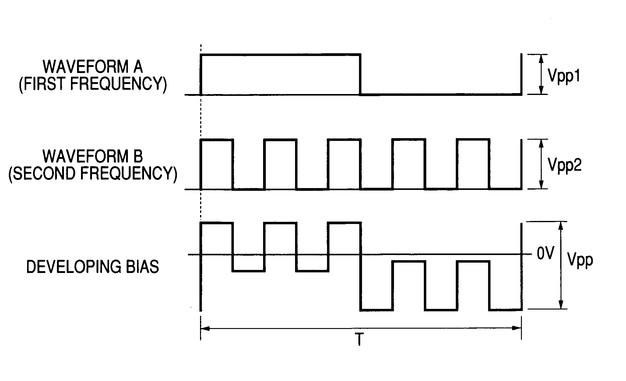
[0034]A development bias was set by superimposing a waveform A of a square wave having a frequency of 1 kHz and an amplitude Vpp1 of 1075 V and a waveform B of a square wave having a frequency of 3 kHz and an amplitude Vpp2 of 325 V on one another to provide an AC component of the development bias on which a DC component Vavg of 220 V was further superposed. The density of an image was measured with the AC component of the development bias set at the above-described conditions relative to a potential Vs of −70 V at the image portion of the photosensitive member and with the average potential Vavg of the DC component varied from −370 V to +530 V, and contrast potential γ-characteristics as shown in FIG. 7 were obtained.

[0035]As shown in FIG. 7, a sufficient image density of 1.45 is obtained at a contrast potential of 150 V, and characteristics are achieved that allow a sufficient image density to be obtained by setting the average potential Vavg of the DC component of the development...

second embodiment

[0038]A development bias was set by superposing a waveform A of a square wave having a frequency of 1 kHz and an amplitude Vpp1 of 600 V and a waveform B of a square wave having a frequency of 5 kHz and an amplitude Vpp2 of 800 V on one another to provide an AC component of the development bias on which a DC component Vavg of 220 V was further superposed. A sufficient image density of 1.45 was obtained at a contrast potential of 180 V. Specifically, a sufficient image density was obtained by setting the average potential Vavg of the DC component of the development bias at −250 V relative to a potential of −70 V at the image portion of the photosensitive member. Fogs on the background of the image were sufficiently reduced by setting the potential Vs at the photosensitive member with a potential difference of −320 V from the average potential Vavg of the DC component of the development bias. Therefore, an image without fogs on the background can be obtained by setting the potential a...


PUM


Abstract

A method of forming an image includes the steps of providing a development bias having a DC component and an AC component superposed on one another and applying the development bias to a developer carrying member. The AC component is provided by superposing a waveform at a second frequency on a waveform at a first frequency in synchronism with each other. The second frequency is an odd multiple of the first frequency.

Description

BACKGROUND OF THE INVENTION[0001]The present invention relates to a method and an apparatus for forming an electrophotographic image for printers, copying machines, and facsimile apparatus in which toner is deposited on an electrostatic latent image formed on an image carrying member to develop the image.[0002]Methods of developing an electrostatic latent image on an image carrying member by applying a development bias having a DC component and an AC component superposed on one another to a developer carrying member is well known by, for example, JP-A-58-32377 and JP-A4-56976.[0003]FIG. 1 is a diagram for explaining a method of applying a development bias of the related art, and it shows a waveform of a development bias in a case wherein an image carrying member is charged at −600 V and development is performed using a negatively charged toner with the image portion charged at a potential of −70 V. One period of the development bias has a time t1 on a development restraining side of...

Claims


Application Information

Patent Timeline
Patent Type & Authority Patents(United States)
IPC IPC(8): G03G15/06G03G15/08
CPCG03G15/065
Inventor OKAMURA, TAKEHIKO
Owner SEIKO EPSON CORP
Why Eureka
Try Eureka