Valve with radial recesses

a valve and recess technology, applied in the direction of fuel injection apparatus, spraying apparatus, feeding system, etc., can solve the problems of varying the injection quantity of fuel injection nozzles, and achieve the effect of reducing wear of the valve, reducing the “wandering” of the valve sealing face, and producing economic effects

Inactive Publication Date: 2006-02-21
ROBERT BOSCH GMBH
View PDF14 Cites 5 Cited by
  • Summary
  • Abstract
  • Description
  • Claims
  • Application Information

AI Technical Summary

Benefits of technology

[0007]One advantage of the present invention is that the “wandering” of the valve sealing face is limited, and the wear of the valve is reduced. This is attained by means of a valve having a valve needle which is axially displaceable in a bore of a valve body and which on one end has a conical valve needle tip. The valve needle tip includes a radial valve sealing face, which in the closing position of the valve comes to rest on a conical inner wall of the valve body on the closed end of the bore. In the inner wall of the valve body there is at least one opening, which connects the bore with the outside of the valve body. The valve includes two radial recesses, which are disposed in the valve needle tip or in the inner wall of the valve body, and one of the radial recesses is located upstream and the other radial recess is located downstream from the position of the valve sealing face, in the closing position of the valve.
[0008]Between the radial recesses there is a seat region, to which the “wandering” of the valve sealing face is limited. In the closing position of the valve, the valve needle tip comes to rest with the valve sealing face in this seat region on the conical inner wall of the valve body and thus seals off the bore upstream of the valve sealing face from the bore downstream of the valve sealing face and thus also from the outside of the valve body. In this connection, the outside of the valve body means the volume into which a flowing liquid or gaseous medium enters when, with the valve open, it emerges from the valve via the valve openings. As wear increases, the valve sealing face can “wander” (with respect to the closing position of the valve) either as far as the upper edge of the first recess downstream or as far as the lower edge of the second recess upstream, but no farther. The recesses prevent the valve needle tip from resting on the inner wall of the valve body at the place where the recesses are made radially in the valve needle tip or the inner wall of the valve body, because the recesses create a spacing between these two components of the valve.
[0009]In a preferred embodiment of the present invention, the conical valve needle tip has a jacket face which includes at least two regions with different cone angles.
[0010]The disposition of the at least two regions of the valve needle tip having the different cone angles, in combination with the positions of the two radial recesses of the invention and with the cone angle of the conical inner wall of the valve body, define the position of the valve needle tip at which the valve sealing face is located.
[0011]The present invention also relates to a method for producing the valve of the invention, in which the recesses are produced by machining a standard valve, for instance by metal-cutting machining. Using standard valves that are used in great quantities means that the valves according to the invention can be produced economically and with little effort.

Problems solved by technology

The metering of the injection quantity by a fuel injection nozzle varies over its service life, because of wear.

Method used


Image

  • Valve with radial recesses
  • Valve with radial recesses

Examples


Embodiment Construction

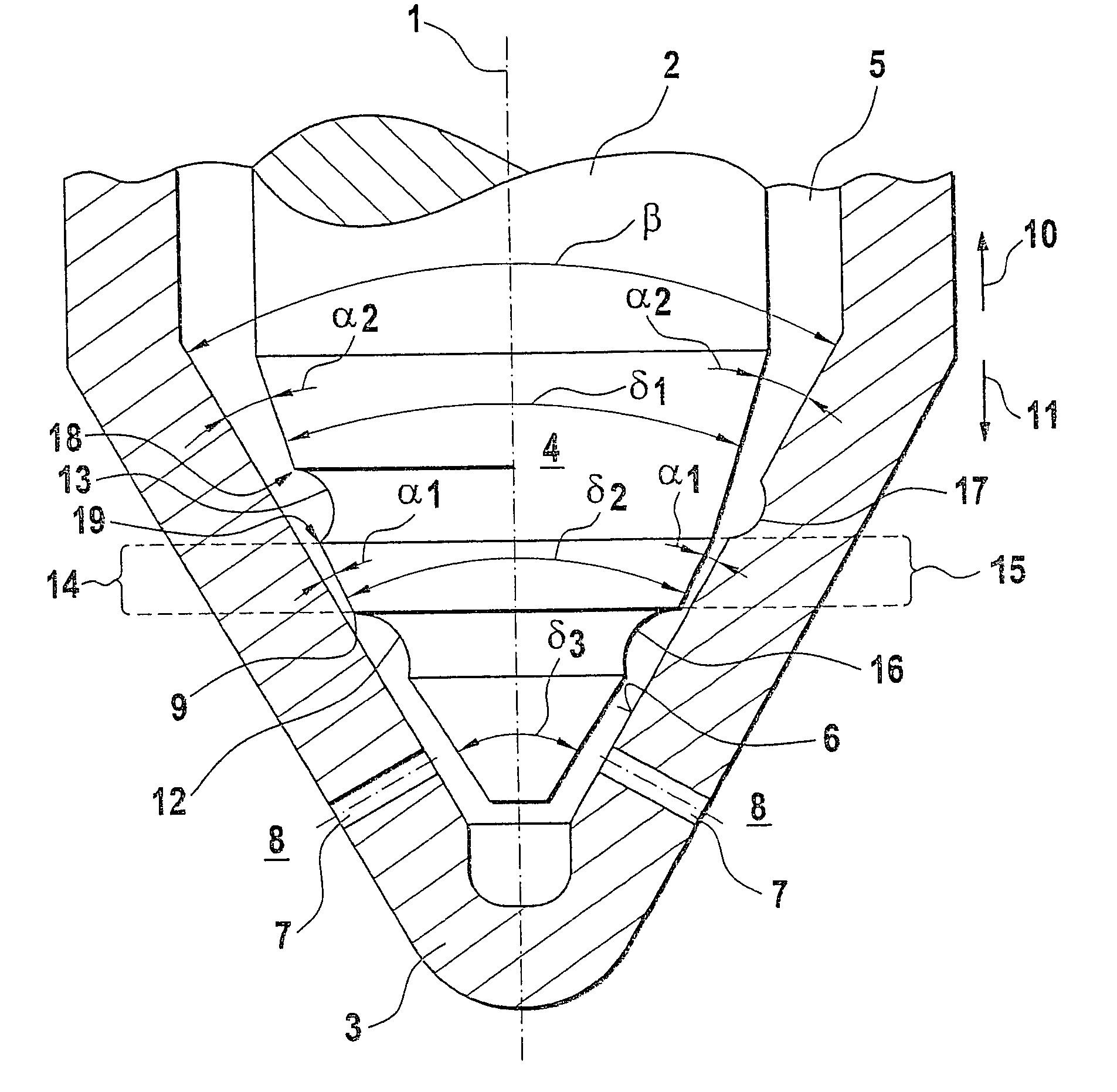
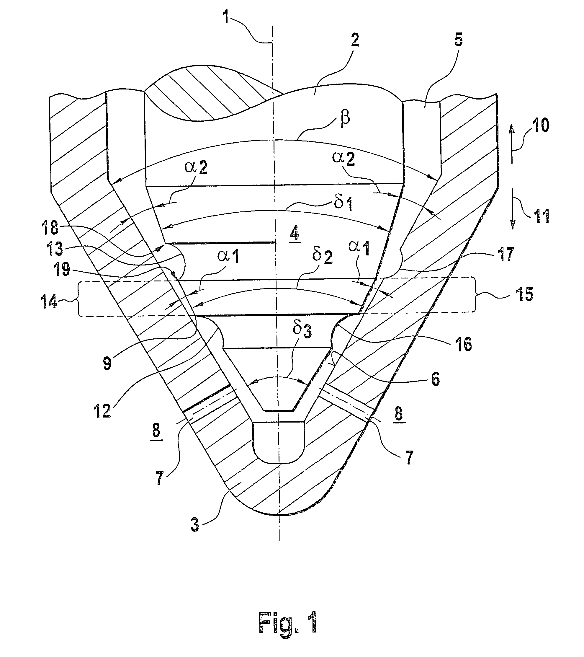
[0014]FIG. 1 shows two variants of the valve of the invention, combined in a single schematic drawing. One variant is shown on the left of the axis of symmetry 1, and the other is shown on the right. The main components of the valve shown are the valve needle 2 and the valve body 3; the valve needle 2 is axially displaceable in the valve body 3. The valve needle 2 has a conical valve needle tip 4 on its end. The valve body 3 includes a bore 5, which tapers conically on its end. Openings 7 are disposed in the conical inner wall 6 of the valve body and, when the valve is open, connect the bore 5 with the outside 8 of the valve body 3.

[0015]In the closing position of the valve, the valve needle tip 4 comes to rest, with a radial valve sealing face 9, on the conical inner wall 6 of the valve body. The valve sealing face 9 takes the form of the jacket face of a truncated cone. When the valve is closed, it rests on the conical inner wall 6 of the valve body and thus seals off the bore 5 u...


PUM


Abstract

A valve having a valve needle axially displaceable in a bore of a valve body and which has a conical valve needle tip having a radial valve sealing face, which in the closing position comes to rest on a conical inner wall of the valve body on the closed end of the bore. In the inner wall of the valve body there is at least one opening which connects the bore with the outside of the valve body. The valve includes two radial recesses disposed in the valve needle tip or in the inner wall of the valve body, and one of the radial recesses is located upstream and the other radial recess is located downstream from the position of the valve sealing face, in the closing position of the valve.

Description

CROSS-REFERENCE TO RELATED APPLICATIONS[0001]This application is a 35 USC 371 application of PCT / DE 02 / 01081 filed on Mar. 23, 2002.BACKGROUND OF THE INVENTION[0002]1. Field of the Invention[0003]Injection nozzles are essential components of self-igniting internal combustion engines. Among their tasks are metered injection, fuel preparation, shaping of the course of injection, and sealing off from the combustion chamber. In common rail Diesel injection systems, along with the main injection a preinjection is effected, which makes it possible to reduce exhaust emissions and noise. The present invention, however, relates not only to fuel injection nozzles but also to all types of nozzles and metering valves.[0004]2. Prior Art[0005]German Patent Disclosure DE 196 34 933 relates to a fuel injection valve for internal combustion engines, with a valve member that is axially displaceable in a bore of a valve body. On its end toward the combustion chamber of the engine, the valve member has...

Claims


Application Information

Patent Timeline
Patent Type & Authority Patents(United States)
IPC IPC(8): F02M61/00F02M45/04F02M47/02F02M61/16F02M61/18
CPCF02M61/1873F02M45/04F02M61/168F02M47/027
Inventor MATTES, PATRICKBOECKING, FRIEDRICH
Owner ROBERT BOSCH GMBH
Why Eureka
Try Eureka