Robotic rack loading apparatus and method

a robot and rack technology, applied in the direction of packaging goods, packaging foodstuffs, manufacturing tools, etc., can solve the problems of damage to panel assemblies and their finished surfaces

Inactive Publication Date: 2006-02-21
GM GLOBAL TECH OPERATIONS LLC
View PDF21 Cites 24 Cited by
  • Summary
  • Abstract
  • Description
  • Claims
  • Application Information

AI Technical Summary

Benefits of technology

[0012]further lowering the tool to a drop off position, the compliant support allowing the panel to be guided by the lead-in surfaces into the set of slots with a minimum of stress;

Problems solved by technology

However, the tolerances in the positioning of the racks, the location of slots in the dunnage, and the manner of the slots being located by the robot all combine to create difficulties in the loading of such panel assemblies, which may result in damage to panel assemblies and their finished surfaces.

Method used


Image

  • Robotic rack loading apparatus and method
  • Robotic rack loading apparatus and method
  • Robotic rack loading apparatus and method

Examples


Embodiment Construction

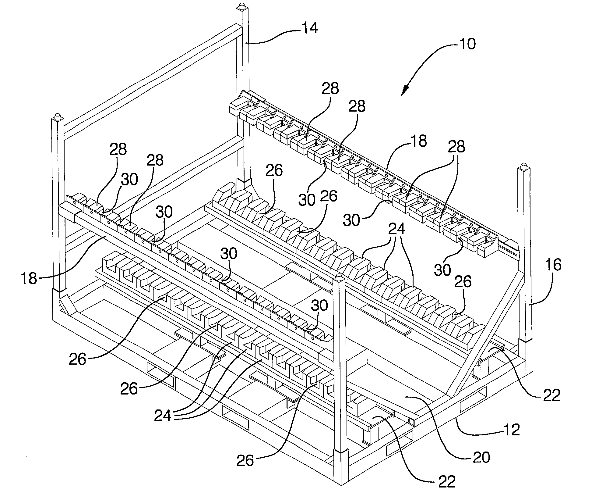
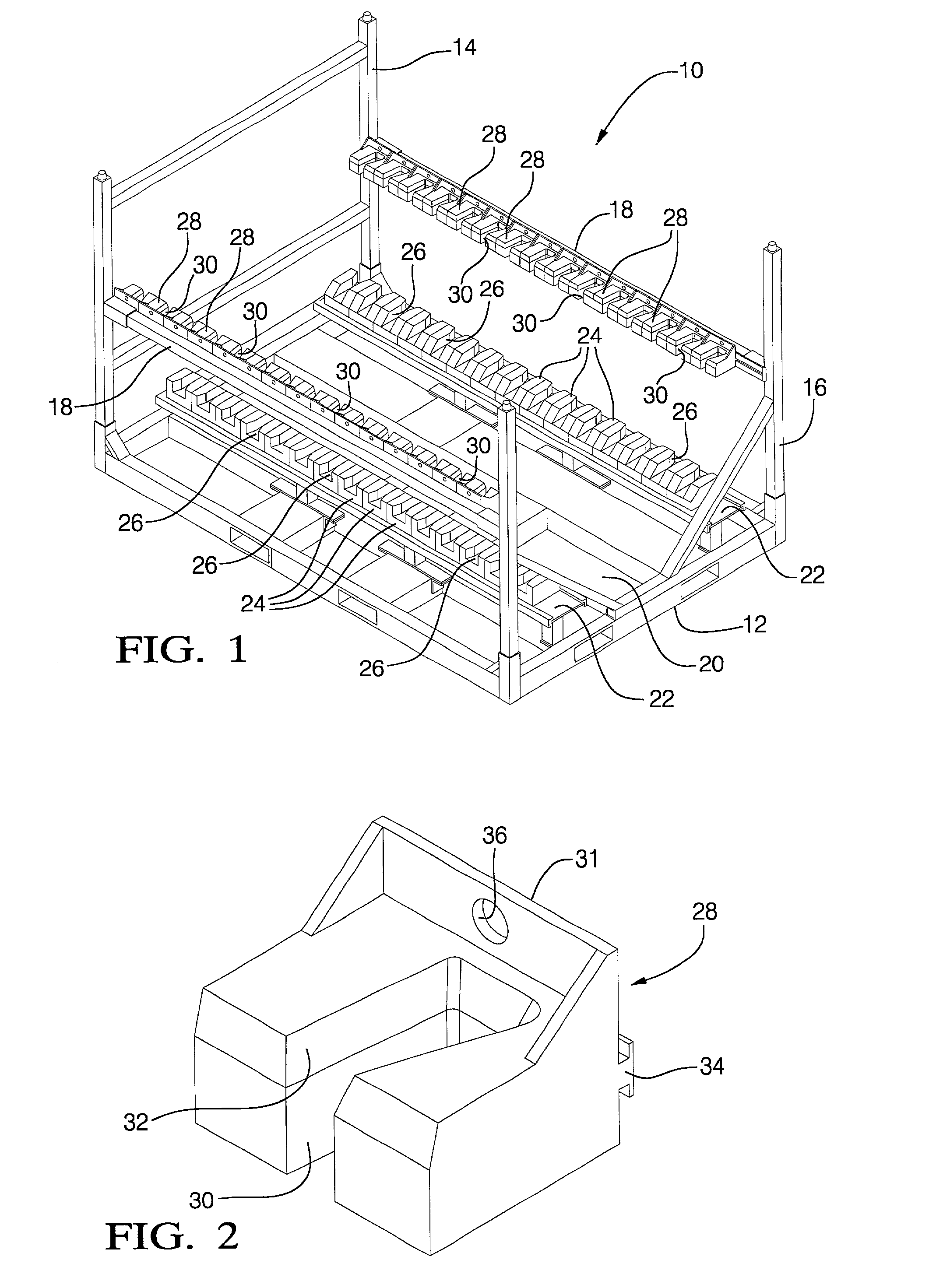
[0021]Referring first to FIG. 1 of the drawings in detail, numeral 10 generally indicates a panel loading rack formed in accordance with the invention. Rack 10 includes a base 12 capable of being picked up by a forklift truck from any side of the rack. The base supports a back 14 and a front 16 connected longitudinally by side support members 18. The front 16 includes an open central portion 20 to permit front entry of a loading tool, and the base includes horizontal support members on which are mounted bottom supports 22.

[0022]The bottom supports are slotted longitudinally to receive a plurality of individual plastic dunnage members 24 having transverse slots 26 opening upward. The side supports 18 are slotted to receive individual plastic dunnage members 28 having vertical slots 30 opening inwardly. Slots 26, 30 are arranged in the rack in sets, each set including two laterally aligned lower transverse slots 26 and two laterally aligned vertical side slots 30 positioned to receive...


PUM


Abstract

Robotic rack loading apparatus and method include features and loading steps that provide essentially damage free rack loading of automotive panel assemblies into a specially designed rack. The rack includes dunnage elements containing sets of slots with lead-in upper edge angles and sensing holes associated with the slots. The robot carries a modified end of arm tool including a sensor to sense the location of a sensing hole to position a panel for loading into a corresponding set of slots. Another sensor preferably senses objects or structure in the rack to position the tool in a preload position. A compliant device allows lateral and longitudinal compliance of the end of arm tool to allow assemblies to be funneled into position in the slots without encountering damaging stress. A programmed robot can thus automatically load panel assemblies into the rack without damage.

Description

TECHNICAL FIELD[0001]This invention relates to robotic rack loading of panel assemblies such as hoods, deck lids, doors and other components such as radiator supports. In particular, the invention relates to a method and apparatus for rack loading of panel assemblies by a programmed robot.BACKGROUND OF THE INVENTION[0002]It is known in the art to provide for the robotic loading of manufactured components into racks for temporary storage. However, the tolerances in the positioning of the racks, the location of slots in the dunnage, and the manner of the slots being located by the robot all combine to create difficulties in the loading of such panel assemblies, which may result in damage to panel assemblies and their finished surfaces. An improved apparatus and method are therefore desired to provide the capability of satisfactorily loading finished panel assemblies into a temporary storage rack without damaging the assemblies.SUMMARY OF THE INVENTION[0003]The present invention provid...

Claims


Application Information

Patent Timeline
Patent Type & Authority Patents(United States)
IPC IPC(8): B65D85/68B25J9/00B25J17/02
CPCB25J17/0208B25J9/0096
Inventor RANSOM, LANCE T.
Owner GM GLOBAL TECH OPERATIONS LLC
Why Eureka
Try Eureka