Reinforced monorail balloon catheter

a dilatation catheter and reinforced monorail technology, applied in balloon catheters, other medical devices, surgery, etc., can solve the problems of reducing the space between the catheter and the guide wire, and reducing the size of the catheter. , the effect of reducing the amount of blood

Inactive Publication Date: 2006-02-21
MEDTRONIC VASCULAR INC
View PDF78 Cites 58 Cited by
  • Summary
  • Abstract
  • Description
  • Claims
  • Application Information

AI Technical Summary

Benefits of technology

The present invention relates to a dilatation catheter used in medical procedures. It has several technical improvements including: adding a strong stiffening wire inside the catheter to increase its durability while maintaining flexibility; providing a larger space between the guide wire and the interior of the guide wire tube to prevent blood clotting and ensure smooth operation; tapering the guide wire tube to decrease its thickness and make it easier to pass through narrow areas in the body. These modifications improve the performance and reliability of the dilatation catheter during various medical procedures.

Problems solved by technology

The technical problem addressed in this patent relates to improving the design of monorail dilatation catheters used in angioplasty procedures. Current versions often have limited stiffness near the site of insertion into the patient's body, making advancement through narrow passages challenging. Additionally, some designs utilize stiffening wires or other components that may buckle or even damage the catheter during use. The invention proposes various improvements including reducing the size of the gap between the guide wire and the catheter, adding a stable reinforcement mechanism to prevent buckling and perforation, and limiting blood entry while still allowing unrestricted movement of the guide wire. These modifications enhance the performance and safety of these important medical devices.

Method used


Image

  • Reinforced monorail balloon catheter
  • Reinforced monorail balloon catheter
  • Reinforced monorail balloon catheter

Examples


Embodiment Construction

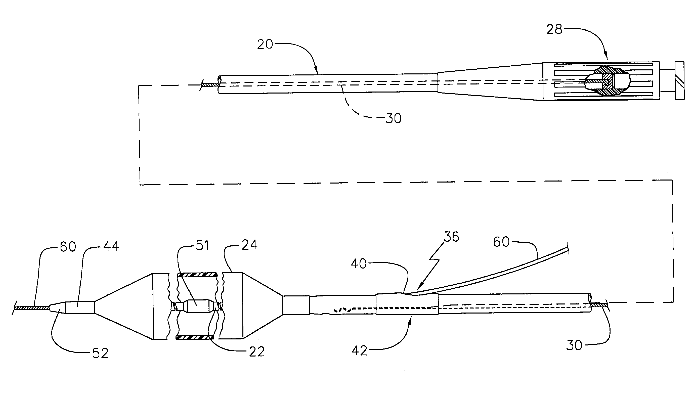
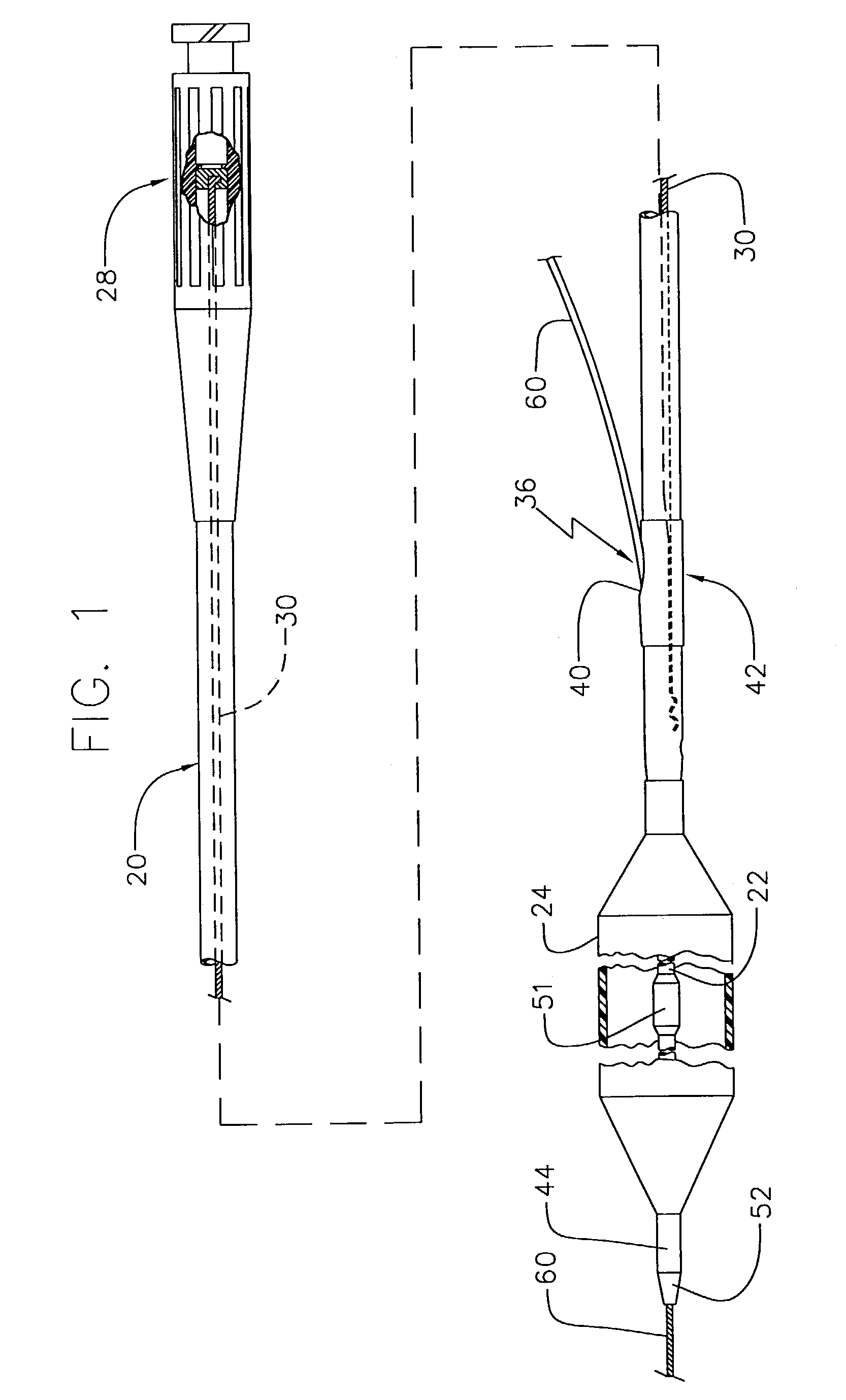
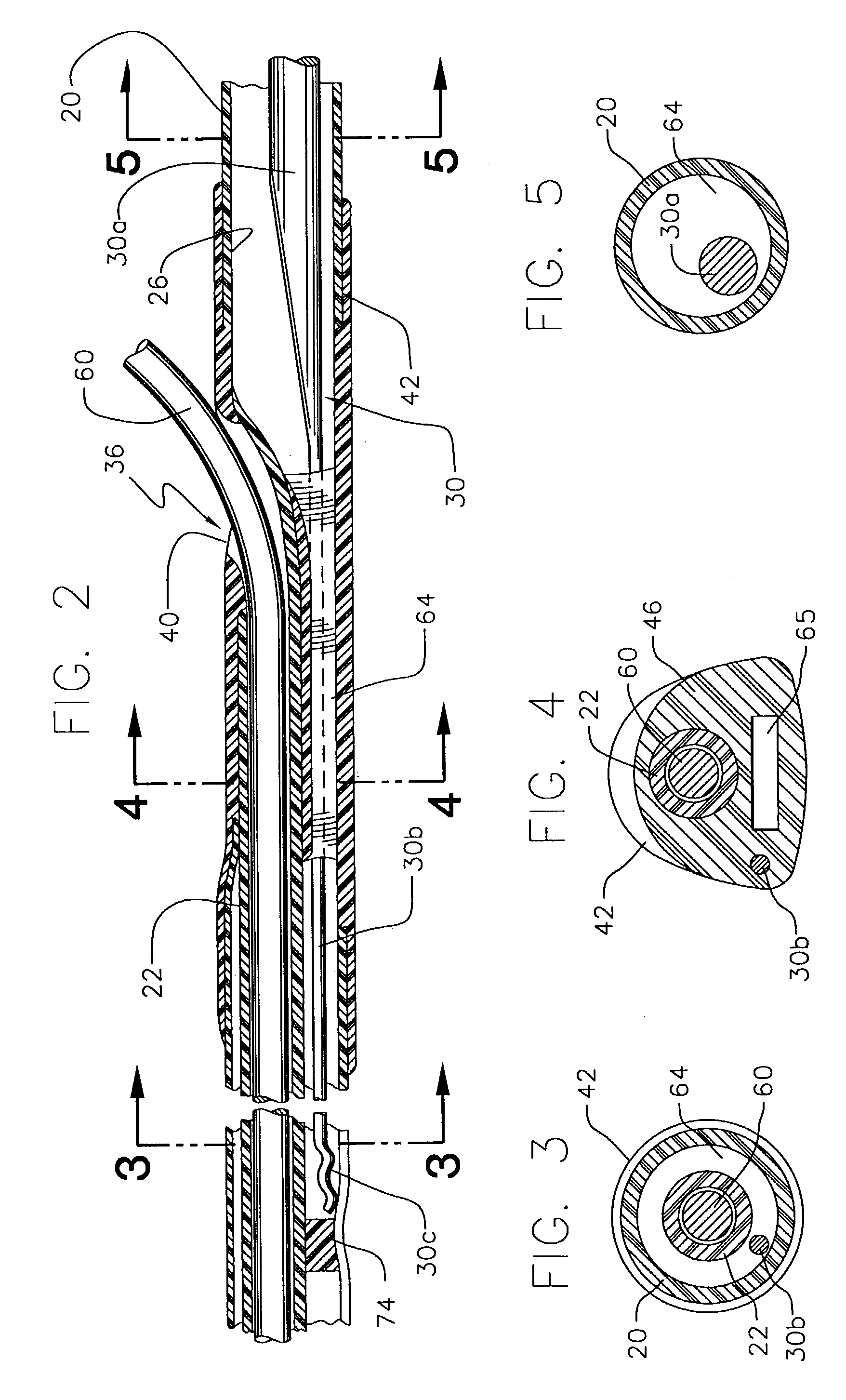
[0025]A preferred embodiment of the invention as illustrated in FIGS. 1 and 2 is a rapid exchange or monorail dilatation catheter comprising an elongated catheter shaft 20, a guide wire tube 22 (FIG. 2) and an angioplasty balloon 24.

[0026]In conventional fashion, the distal end of balloon 24 is attached to the distal portion of the guide wire tube 22 and the proximal portion of the balloon is attached to the distal portion of the catheter shaft 20. The balloon 24 is formed from suitable balloon material, for example, polyethylene terephthalate (“PET”), nylon, or urethane. It is preferred that the balloon 24 be coated with a highly lubricous, abrasion resistant coating. An example of this preferred coating is that disclosed in U.S. Pat. No. 5,077,352 to Elton, and assigned to the assignee of the present invention, C. R. Bard, of Murray Hill, N.J. The Elton '352 patent is incorporated by reference as if set forth in its entirety herein.

[0027]As shown if FIG. 7, the wall thickness of t...


PUM


Abstract

The invention is a dilation catheter which comprises an elongated catheter shaft, a guide wire tube, and an angioplasty balloon. The distal end of the balloon is attached to the distal portion of the guide wire tube, and the proximal portion of the balloon is attached to the distal portion of the catheter shaft. A stiffening wire is attached to the inner wall of the catheter shaft at a plurality of points along its length. The distal extremity of the guide wire tube is decreased in size relative to the proximal portion of the guide wire tube. A fluid is contained within the guide wire lumen.

Description


Claims


Application Information

Patent Timeline
Owner MEDTRONIC VASCULAR INC
Why Eureka
Try Eureka