Intravascular flow restrictor

a technology of flow restrictor and stent, which is applied in the field of intravascular devices, can solve the problems of increasing the pressure on the right side of the heart, excessive blood flow to the lungs, and the more difficult job of the left side of the heart to pump blood all around the body, and achieves the effect of inhibiting the unraveling of the strands

Inactive Publication Date: 2006-02-21
ST JUDE MEDICAL CARDILOGY DIV INC
View PDF5 Cites 140 Cited by
  • Summary
  • Abstract
  • Description
  • Claims
  • Application Information

AI Technical Summary

Benefits of technology

[0012]In accordance with the present invention, there is provided a device that is adapted to be placed and anchored within the vascular system using a transvascular approach for restricting or limiting blood flow to the lungs, liver or other organs. It comprises a collapsible medical device made from a plurality of metal strands that are braded into a woven metal fabric having a proximal end and a distal end, each end having a clamping member for securing each end of the woven metal fabric to thereby gather the strands and inhibit unraveling of the strands. The woven metal fabric has an expanded, ...

Problems solved by technology

In the normal heart, the right side pumps blood to the lungs, which is a relatively easy task, while the left side of the heart has the more difficult job of pumping blood all around the body.
There are a number of heart defects in which there is excessive blood flow to the lungs.
This results in an increase in the pressure on the right and causes too much blood to be pumped to the lungs.
Over a period of time, this narrowing of the pulmonary arteries causes a thickening of the pulmonary arteries due to the increased workload, which leads ultimately to closure of smaller lung arteries which further reduces the blood flow into the lungs.
This process is called pulmonary vascular disease and ultimately results in low oxygen levels and cyanosis and increased hemoglobin levels in the blood of the patient.
For example, in the case of ventricular septal defec...

Method used


Image

  • Intravascular flow restrictor
  • Intravascular flow restrictor
  • Intravascular flow restrictor

Examples


Embodiment Construction

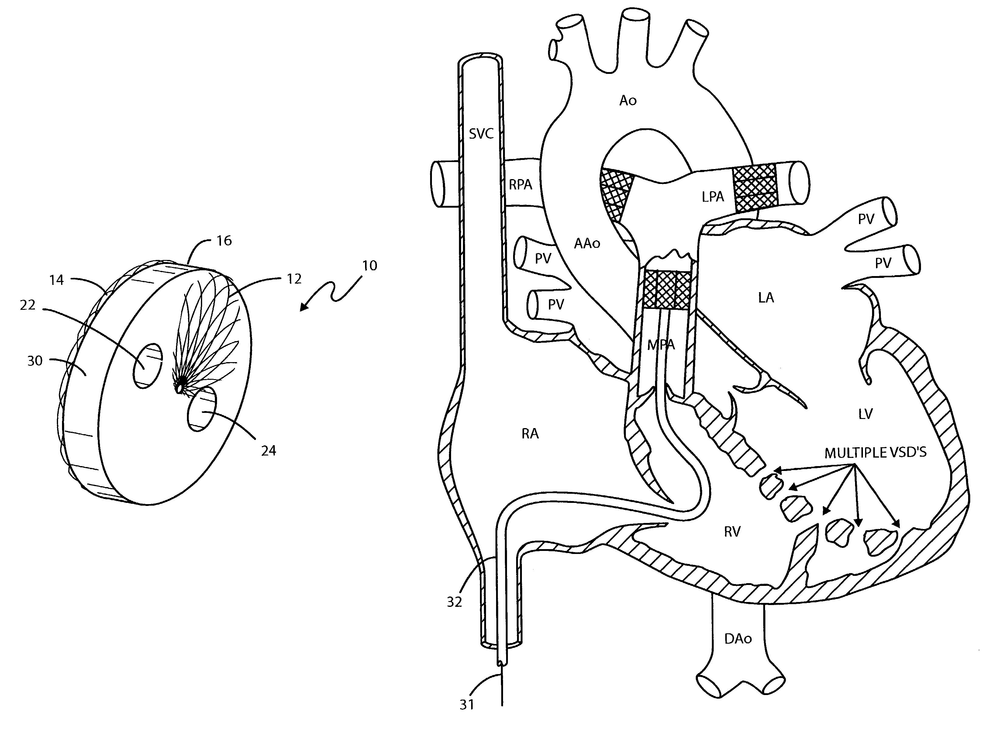
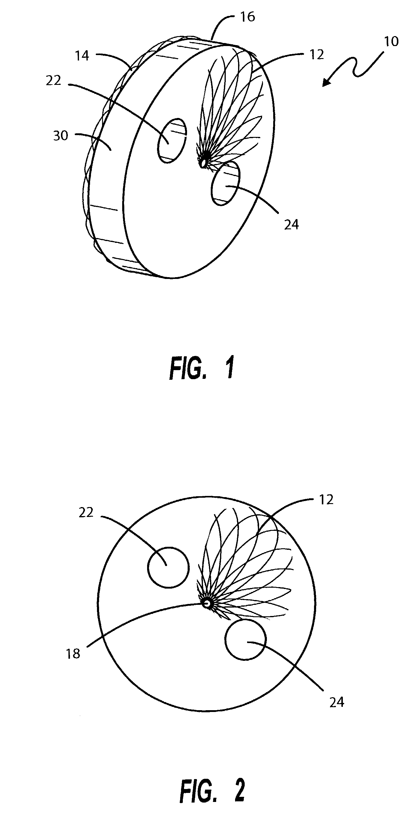
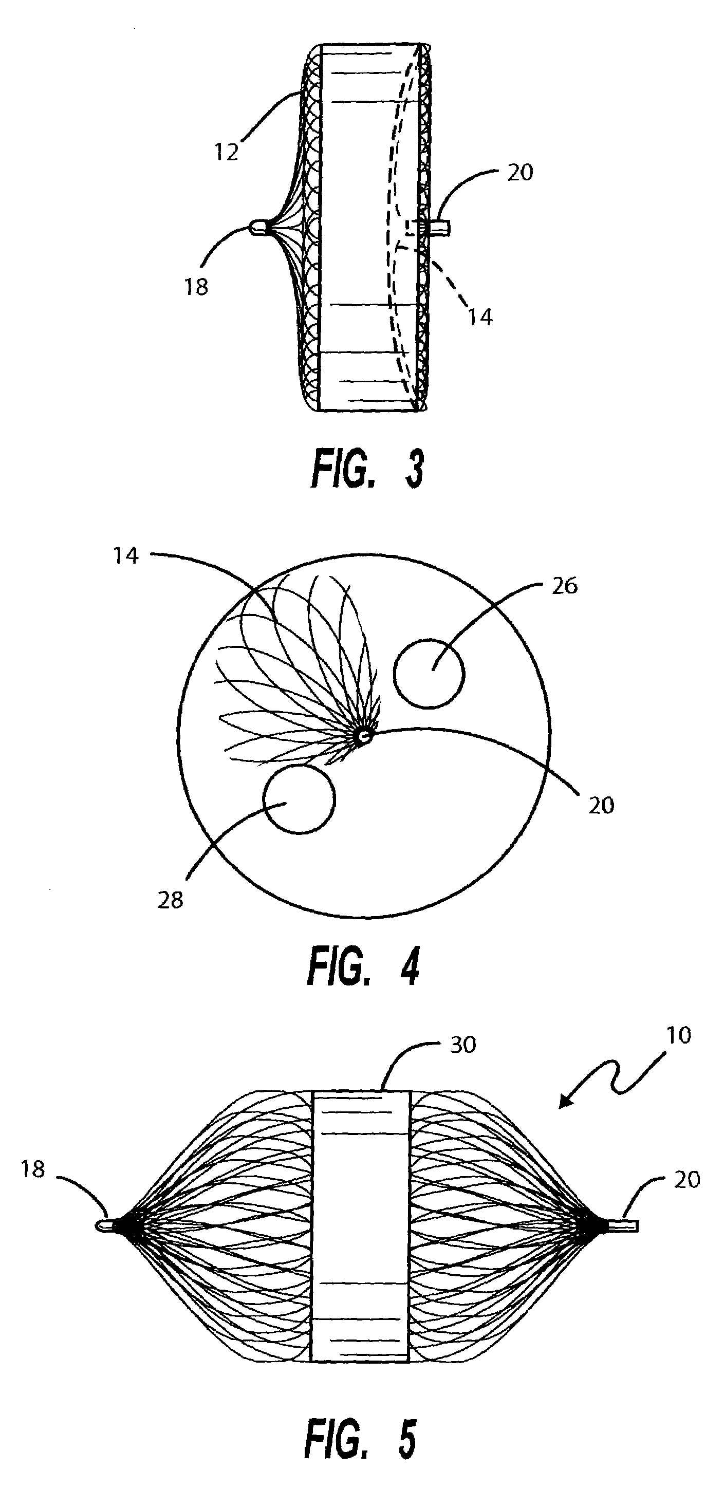
[0022]The present invention provides a percutaneous catheter directed treatment of patients having malformed vascular system structures, such as shunt paths between the left and right side of the heart, transposition of the great arteries (TGA), transhepatic portosystemic shunts and protein-losing enteropathy following a Fontan operation.

[0023]As is illustrated in FIG. 1, the device, when in its unconstrained state, comprises a disk-like device 10 having opposed ends 12 and 14 of a predetermined expanded diameter and a hollow central portion 16 between the two ends. The metal fabric from whom the device 10 is formed comprises a plurality of wire strands that are woven or braided into a tubular configuration and then heat set in a mold in a manner described in U.S. Pat. No. 6,123,715 to Curtis Amplatz, the contents of which are hereby incorporated by reference.

[0024]As is described in the '715 patent, the wire strands comprising the metal fabric are preferably formed from a metal or ...


PUM


Abstract

An intravascular flow restrictor comprises a braided tubular structure designed to be placed in the main pulmonary artery for limiting blood pressure in the lungs. The braided structure is designed to be collapsed for placement in a delivery catheter but when ejected from the delivery catheter, assumes a substantially larger diameter disk shaped device having one or more longitudinal channels or passways therethrough.

Description

CROSS-REFERENCE TO RELATED APPLICATION[0001]This application is a divisional of application Ser. No. 10 / 087,570, filed Mar. 1, 2002 now U.S. Pat. No. 6,638,257, and entitled “INTRAVASCULAR FLOW RESTRICTOR”.BACKGROUND OF THE INVENTION[0002]I. Field of the Invention[0003]The present invention relates generally to intravascular devices for treating certain medical conditions, and, more particularly, relates to an intravascular flow restrictor for reducing blood pressure down stream of the location where the flow restrictor is placed.[0004]II. Description of the Prior Art[0005]In the normal heart, the right side pumps blood to the lungs, which is a relatively easy task, while the left side of the heart has the more difficult job of pumping blood all around the body. As a result, the pressure in the left ventricle (pumping chamber) is generally about five times that in the right ventricle, and the wall of the left ventricle is thicker than that of the right. There are a number of heart d...

Claims


Application Information

Patent Timeline
IPC IPC(8): A61B17/08A61B17/00A61B17/12A61F2/06A61F2/90
CPCA61B17/12022A61B17/12036A61B17/12109A61B17/12122A61B17/12172A61F2002/068A61B2017/00243A61B2017/00557A61B2017/1205A61F2/90A61M29/00A61M29/02
Inventor AMPLATZ, KURT
Owner ST JUDE MEDICAL CARDILOGY DIV INC
Why Eureka
Try Eureka