Cleaning device

a cleaning device and cleaning technology, applied in the direction of carpet cleaners, instruments, photosensitive materials, etc., can solve the problems of difficult to maintain a stable cleaning performance, damage to carpets, and inability to roll adhesive rolls, etc., to achieve stable cleaning of carpets and flooring for a long time.

Inactive Publication Date: 2006-02-28
KAO CORP
View PDF13 Cites 11 Cited by
  • Summary
  • Abstract
  • Description
  • Claims
  • Application Information

AI Technical Summary

Benefits of technology

[0014]An object of the present invention is to make it possible to stably clean the carpet and the flooring for a long time.
[0015]Another object of the present invention is to improve an operability of a cleaning device by a user, and improve a performance of picking up dust.

Problems solved by technology

(1) When cleaning a carpet using the adhesive roll, the adhesive roll adheres fibers constituting the carpet, thereby damaging the carpet.
(2) When cleaning a flooring using the adhesive roll, the adhesive roll strongly adheres the flooring so as to be immobilized, thereby making it impossible to roll the adhesive roll.
(3) Since hairs or the like become wound around the brush body, it is hard to maintain a stable cleaning performance.
In this prior art, the following problems exist.
(1) Since the electrostatic generating roller rolls while pressing the carpet from a surface thereof, it is impossible to pick up dust in a deep portion of the fiber of the carpet, so that it is hard to improve a cleaning performance.
(2) When making an adhesive force of the adhesive roll strong in order to securely adhere the dusts attached to the electrostatic generating roller to the adhesive roll, the electrostatic generating roller adheres to the adhesive roll, whereby a rotation operating force applied to the electrostatic generating roller by a user becomes heavy.

Method used


Image

  • Cleaning device
  • Cleaning device
  • Cleaning device

Examples


first embodiment

[0025](First Embodiment) (FIGS. 1 to 4)

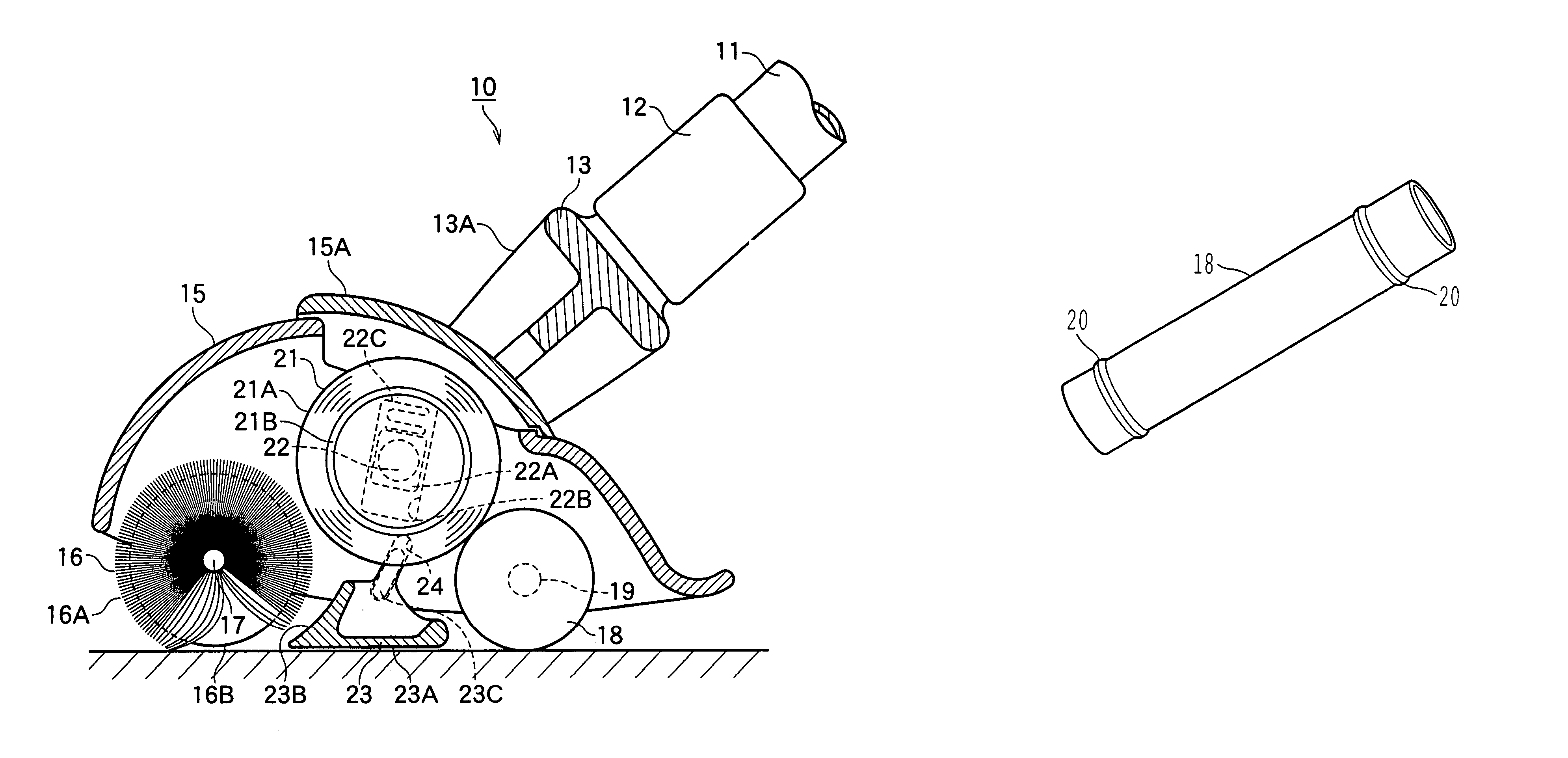
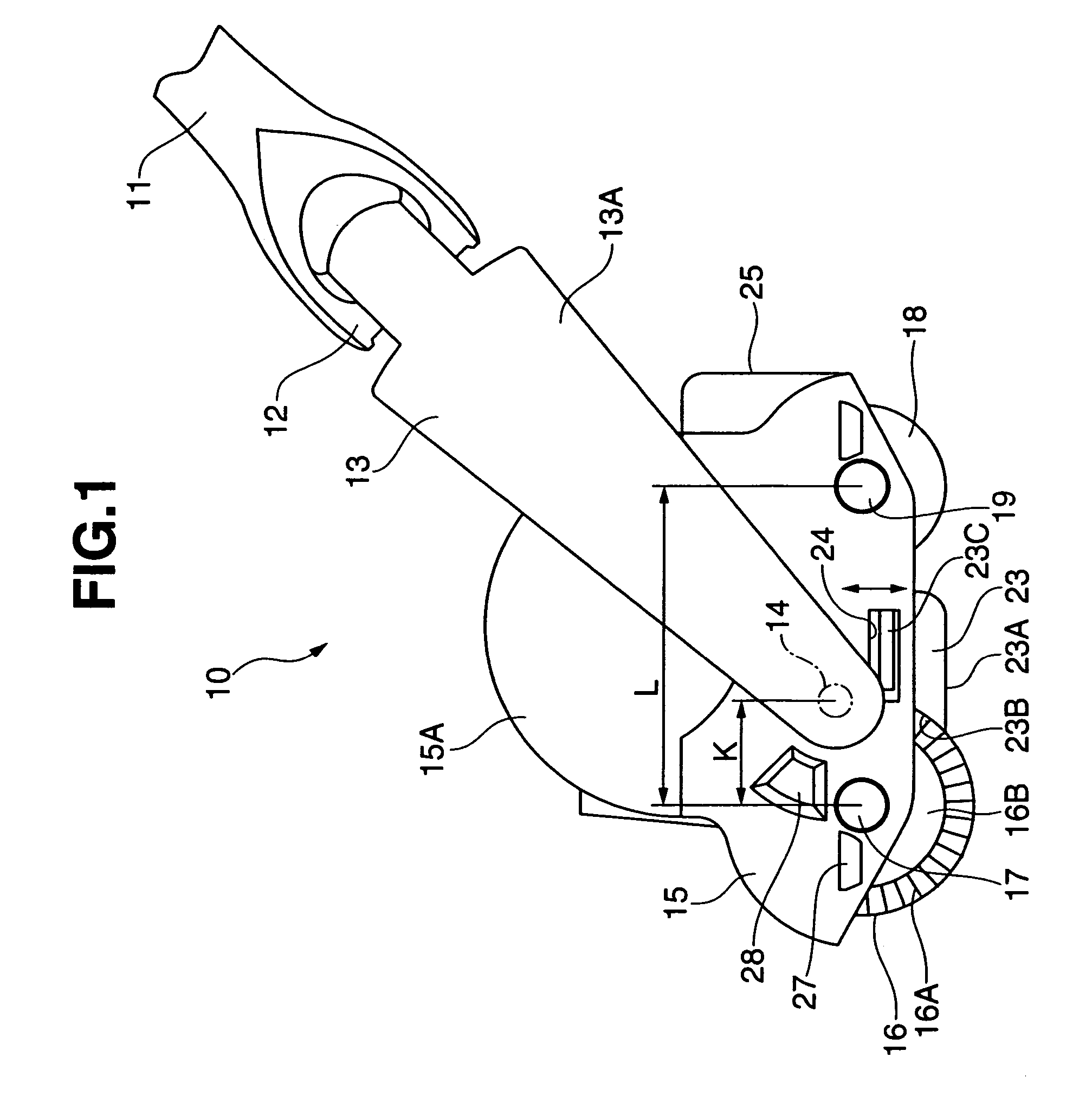
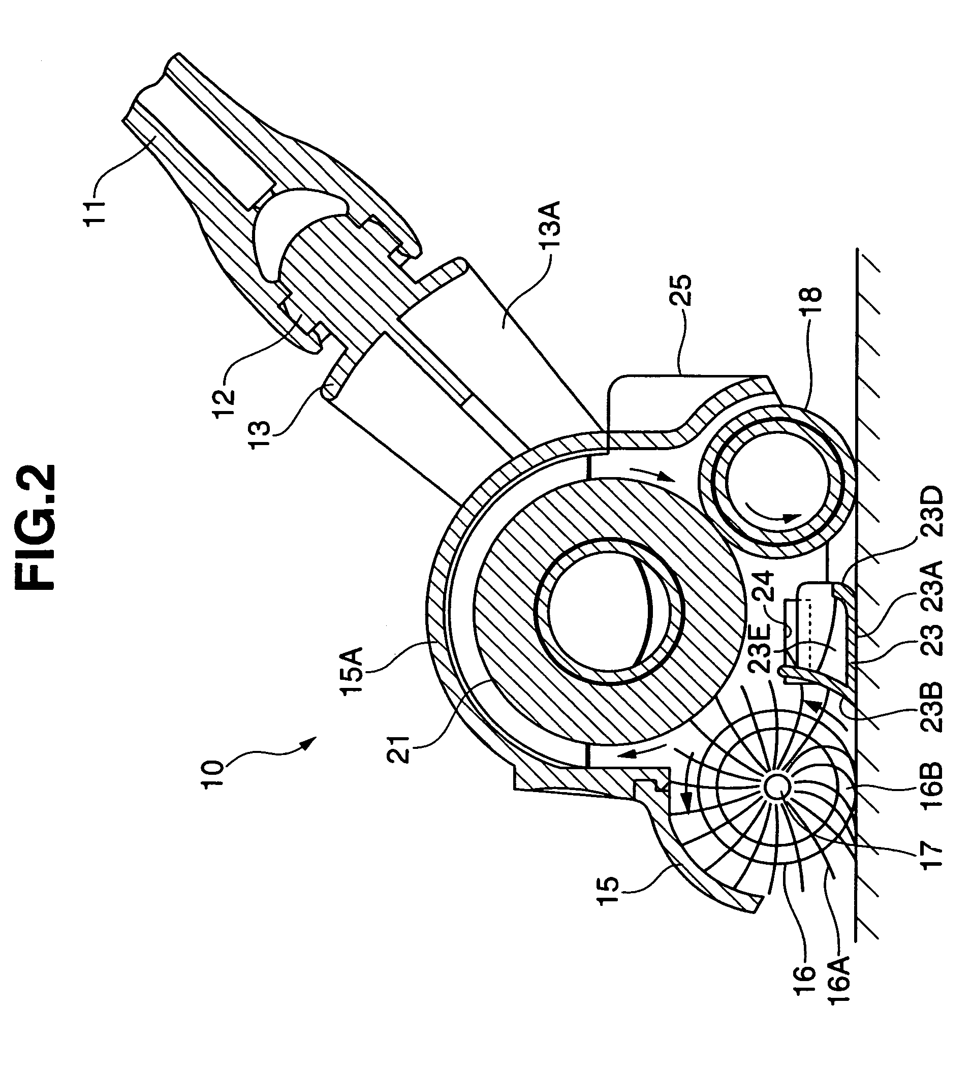
[0026]A cleaning device 10 is structured, as shown in FIGS. 1 and 2, such that a supporting arm 13 is connected to a front end portion of a handle 11 via a joint portion 12 in such a manner as to freely swing in a lateral direction, and a frame 15 is supported to both side arm portions 13A of the supporting arm 13 via a supporting shaft portion 14 in such a manner as to freely swing in a longitudinal direction.

[0027]A scraping up body 16 constituted by a brush is rotatably supported at a front portion of the frame 15 via a rotational shaft 17, a contact rotating body 18 constituted by a roll body is in contact with an adhesive roll 21 and capable of rotating with the adhesive roll 21 is rotatably supported at a rear portion of the frame 15 via a rotational shaft 19. The scraping up body 16 and the contact rotating body 18 are arranged in parallel. The scraping up body 16 is constituted by a scraping up portion 16A (a brush portion) and a tire p...

second embodiment

[0059](Second Embodiment) (FIGS. 5 and 6)

[0060]In a second embodiment, the same reference numerals are applied to the same elements as those of the first embodiment and the description thereof will be omitted.

[0061]In the second embodiment, the adhesive roll 21 is rotatably supported on the scraping up body 16 and the contact rotating body 18 via the rotational shaft 22 so as to ride over them in such a manner as to be freely rotated in parallel thereto, and the adhesive roll 21 rotates so as to interlock with the rotation of the scraping up body 16 and the contact rotating body 18. A take in and out port for the adhesive roll 21 is provided in an upper portion of the frame 15 and is covered by a detachable transparent cover 15A. The adhesive roll 21 may be a take-up roll of an adhesive sheet or an adhesive elastomer surface reusable by being cleaned. The adhesive roll 21 in accordance with the present embodiment is constituted by a take-up roll having an adhesive sheet 21A wound ar...


PUM


Abstract

In a cleaning device, the scraping up body and the rotating body rolling the adhesive roll are rotatably supported to the frame, and the adhesive roll is rotatably arranged on the scraping up body and the rotating body in parallel.

Description

CROSS REFERENCE TO RELATED APPLICATIONS[0001]The present application is a division of U.S. application Ser. No. 09 / 984,766 filed Oct. 31, 2001, now U.S. Pat. No. 6,783,600 and is based on Japanese patent application No. 2000-335014 filed on Nov. 1, 2000, No. 2002-031547 filed on Feb. 7, 2001, No. 2001-114645 filed on Apr. 12, 2001, No. 2001-114646 filed on Apr. 12, 2001 and No. 2001-315995 filed on Oct. 12, 2001 each of which is incorporated herein by reference in its entirety.BACKGROUND OF THE INVENTION[0002]1. Field of the Invention[0003]The present invention relates to a cleaning device.[0004]2. Description of the Related Art[0005]As a cleaning device, there is known a structure in which a brush body and an adhesive roll are independently provided and which independently collect dust (Japanese Utility Model Application Laid-open No. 59-139261), and a structure in which an adsorption surface of a primary adsorbing roller and an adhesive sheet of a secondary adsorbing roller are ro...

Claims


Application Information

Patent Timeline
Patent Type & Authority Patents(United States)
IPC IPC(8): A47L11/33A47L11/22A47L11/00A47L11/24A47L25/00
CPCA47L11/22A47L11/33A47L11/4036A47L25/005A47L11/4077A47L11/4091A47L11/4041A47L11/00
Inventor TAWARA, HIROTOSHINODA, YUKIO
Owner KAO CORP
Why Eureka
Try Eureka