

Robot used for cleaning building curtain wall and capable of widening applicable guide range
A robot and cleaning technology, applied in cleaning machinery, construction, cleaning equipment, etc., can solve the problems of impacting the glass curtain wall, poor cleaning effect, difficult to erase stubborn stains on the surface of the curtain wall, etc., and achieve good cleaning effect and high degree of automation.
- Summary
- Abstract
- Description
- Claims
- Application Information
AI Technical Summary
Problems solved by technology
Method used
Image

Examples
Embodiment 1
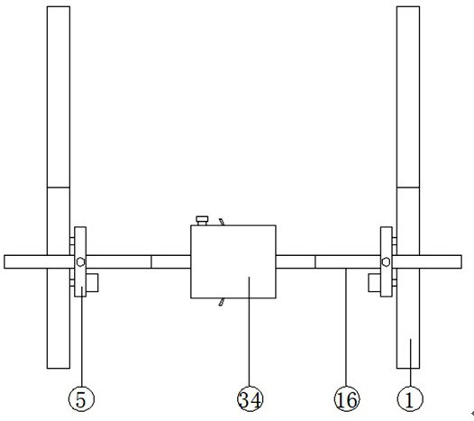
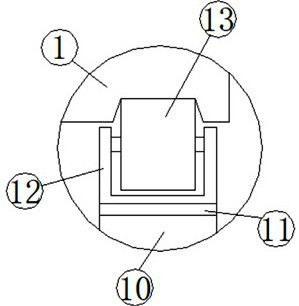
[0039] see Figure 1-12 , according to an embodiment of the present invention, a robot that can increase the applicable guiding range for building curtain wall cleaning includes a longitudinal guide rail assembly, a longitudinal drive device, a transverse guide rail assembly, a lateral drive device and a cleaning device, and the number of the longitudinal guide rail assemblies Two and arranged in parallel, the longitudinal guide rail assembly is spliced by a number of longitudinal guide rails 1 connected end to end, grooves are opened on one side of the longitudinal guide rail 1, and a number of suction cups 2 are fixed at the bottom of the longitudinal guide rail 1, One end of the longitudinal guide rail 1 is provided with two first clamping slots 3, and the other end of the longitudinal guide rail 1 is fixed with a first clamping column 4 matching the first clamping slots 3. The longitudinal driving device includes a first fixed plate 5, and two first bearings 6 are fixedl...
Embodiment 2
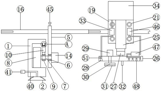
[0042] see figure 2 , 4 and 6, for the suction cup 2, the suction cup 2 is connected with an air intake pipe 40, and the end of the air intake pipe 40 away from the suction cup 2 is provided with a valve 41; for the elastic connector 10, the elastic connection The part 10 includes a sliding cylinder 42, and a sliding rod 43 is provided for sliding in the sliding cylinder 42, and the lower end of the sliding rod 43 is fixedly connected with the outer wall of the first bearing 6, and the inner wall of the lower end of the sliding cylinder 42 is fixedly provided with a stop ring, The outer wall of one end of the sliding rod 43 extending into the sliding tube 42 is fixedly sleeved with a spring 44, and the upper end of the spring 44 is fixedly connected with the inner wall of the upper end of the sliding tube 42; for the locking device, the locking device includes A threaded hole and a locking bolt 45 , the rectangular slot 15 is provided with a threaded hole and the threaded ho...
Embodiment 3
[0045] see figure 2 , 8 and 9, for the air-drying device, the air-drying device includes an air pump 46, a heating cylinder 47 and an air spray head 48, the air pump 46 is fixed on the outer wall of the second fixed plate 19, and the heating cylinder 47 is fixed on the second fixed plate 19 On the four fixed plates 26, the fourth fixed plate 26 is fixedly embedded with a plurality of air spray heads 48 under one end away from the water spray head 28, and the output end of the air pump 46 is connected to one end of the heating cylinder 47 through a gas pipe, so that The air jets 48 are all connected to the other end of the heating cylinder 47 through a gas pipe, and the air pump 46 is electrically connected to the processor 37; for the heating cylinder 47, the upper and lower inner walls of the heating cylinder 47 are symmetrically fixed Electrical connectors, heating wires are provided between the corresponding electrical connectors, and the heating wires are electrically co...
PUM
 Abstract
Description
Claims
Application Information