Controlled fluid energy delivery burst cartridge

Inactive Publication Date: 2006-02-28
MARTIN ELECTRONICS
View PDF40 Cites 44 Cited by
  • Summary
  • Abstract
  • Description
  • Claims
  • Application Information

AI Technical Summary

Benefits of technology

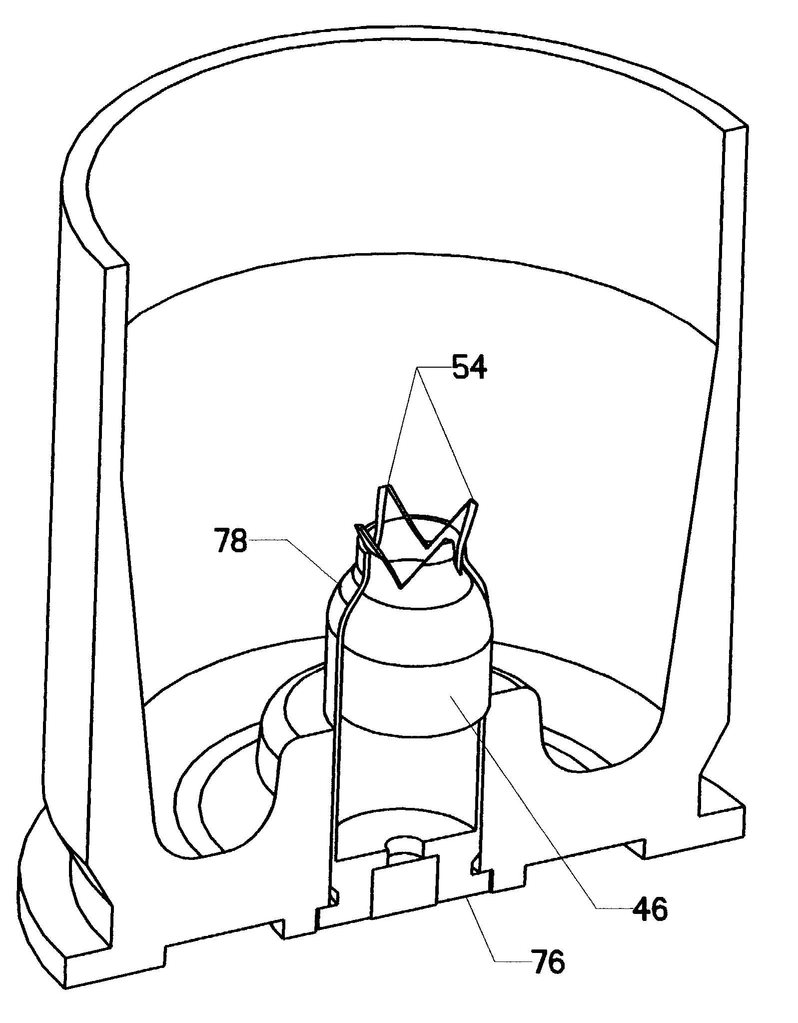
[0016]In operation, the propellant is ignited to produce pressure within the sealed case. This pressure builds steadily until the scribed cross in the burst cap ruptures. The propellant gases are then vented in a metered fashion through the ruptured burst cap. However, the burst cap is retained by the case so that no solid object escapes the high pressure cartridge. In addition, by carefully designing the shape of the burst cap and the components of the low pressure chamber, it is possible to create an efficient expansion nozzle to better meter the propellant gases.

Problems solved by technology

However, the burst cap is retained by the case so that no solid object escapes the high pressure cartridge.

Method used


Image

  • Controlled fluid energy delivery burst cartridge
  • Controlled fluid energy delivery burst cartridge
  • Controlled fluid energy delivery burst cartridge

Examples


Embodiment Construction

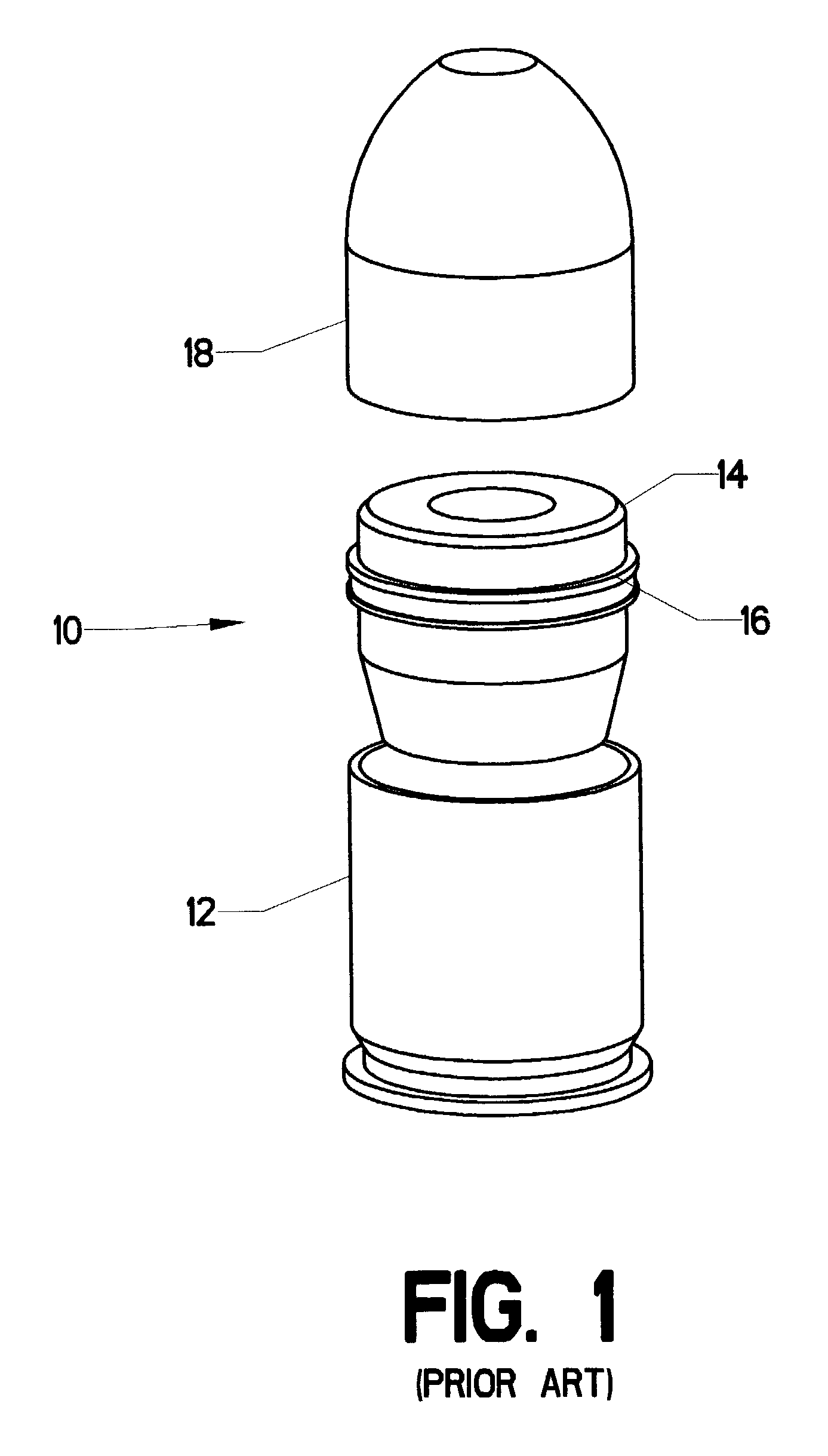
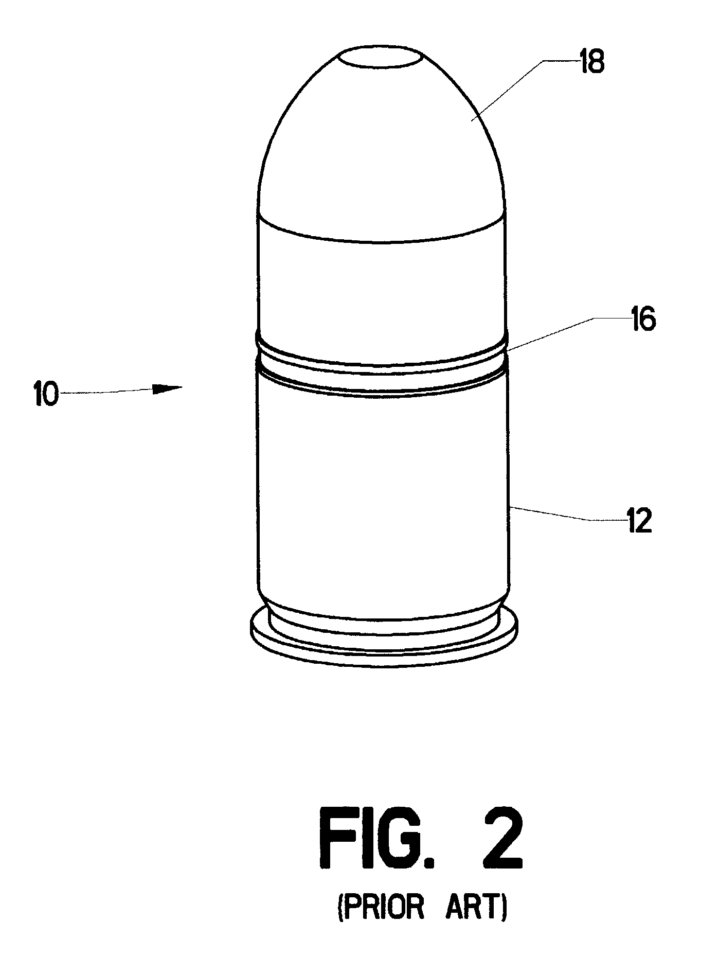
[0038]FIG. 1 shows a prior art practice round 10 (containing marking dye) for a grenade launching weapon. It has three major inert components: case 12, projectile body 14, and nose cone 18. FIG. 2 shows the components assembled as they normally would be prior to firing. FIG. 3 is a section view, showing some internal features of the prior art practice round 10. Low pressure case 12 is formed of base 24 with an attached cylindrical side wall 26. Extraction flange 22 extends out from base 24. It provides an engagement point for an extracting mechanism to pull the round free of the weapon.

[0039]Charge casing 28 extends upward from base 24. Bulkhead 60 closes the upper portion of charge casing 28. It is pierced by charge vent hole 52. Low pressure case 12 is typically formed as one integral piece—either as a metallic casting or as molded plastic.

[0040]Charge casing 28 and bulkhead 60 combine to form a structure to support blank cartridge 32. Blank cartridge 32 supplies high pressure pro...


PUM


Abstract

A modified gas delivery cartridge. A conventional straight-sided brass cartridge case is primed and then filled with solid propellant. A burst cup is then inserted in the case mouth. The burst cup is embossed with a cross or other shape to promote predictable rupture. Once the burst cup is in place, the upper edges of the cartridge case are rolled over the burst cup. In operation, the propellant is ignited to produce pressure within the sealed case. This pressure builds steadily until the embossed cross in the burst cup ruptures. The propellant gases are then vented in a metered fashion through the ruptured burst cup. However, the burst cup is retained by the case so that no solid object escapes the high pressure cartridge. In addition, by carefully designing the shape of the burst cup and the components surrounding it, it is possible to create an efficient expansion nozzle to better meter the propellant gases.

Description

[0001]This invention relates to the field of propellant gas delivery systems. More specifically, the invention comprises an energy delivery cartridge with a burst cap that allows controlled discharge of the propellant gases generated within said cartridge.DESCRIPTION OF THE RELATED ART[0002]Metallic cartridges have been used to encapsulate solid propellants for many years. In recent years other materials have been substituted for the traditional brass, but the principles of operation remain the same: A projectile is seated in the open mouth of a cartridge case containing solid propellant. Ignition of the propellant is provided by percussive or electrical means. The burning propellant generates pressurized gas which forces the projectile out of the mouth of the case and then typically through a barrel bore.[0003]A representative metallic cartridge design is found in the NATO 5.56×45 mm rifle cartridge. In that design, 24 grains of propellant are used to accelerate a 62 grain projecti...

Claims


Application Information

Patent Timeline
Patent Type & Authority Patents(United States)
IPC IPC(8): F42B5/00F42B5/02
CPCF42B5/02
Inventor VAN STRATUM, BRUCE G.
Owner MARTIN ELECTRONICS
Why Eureka
Try Eureka