Rear cushion installation structure of low floor type vehicle

a low floor type, rear cushion technology, applied in the direction of roofs, cycle equipment, cycles, etc., can solve the problem of limiting the effective utilization of space under the seat, and achieve the effects of enhancing driving stability, miniaturizing suspension structure, and center of gravity

Inactive Publication Date: 2006-02-28
HONDA MOTOR CO LTD
View PDF14 Cites 19 Cited by
  • Summary
  • Abstract
  • Description
  • Claims
  • Application Information

AI Technical Summary

Benefits of technology

[0019]As the body frame is a diamond type frame, the engine is suspended by the diamond type frame, the engine can function as a part of the body frame. Therefore, a frame member is not required to be arranged under the engine. Therefore, the engine can be lowered maximally, up to the height of the ground. The center of gravity of the low floor type vehicle is lowered by lowering the engine and driving stability can be enhanced.
[0020]Further, as the rear cushion for the rear wheel is arranged along the rear of the upper frame of the diamond type frame, the rigidity of the rear cushion for the rear wheel can be sufficiently secured by the rigid upper frame and suspension structure can be miniaturized.

Problems solved by technology

Therefore, there is a limit for effectively utilizing space under the seat 353.

Method used


Image

  • Rear cushion installation structure of low floor type vehicle
  • Rear cushion installation structure of low floor type vehicle
  • Rear cushion installation structure of low floor type vehicle

Examples


Embodiment Construction

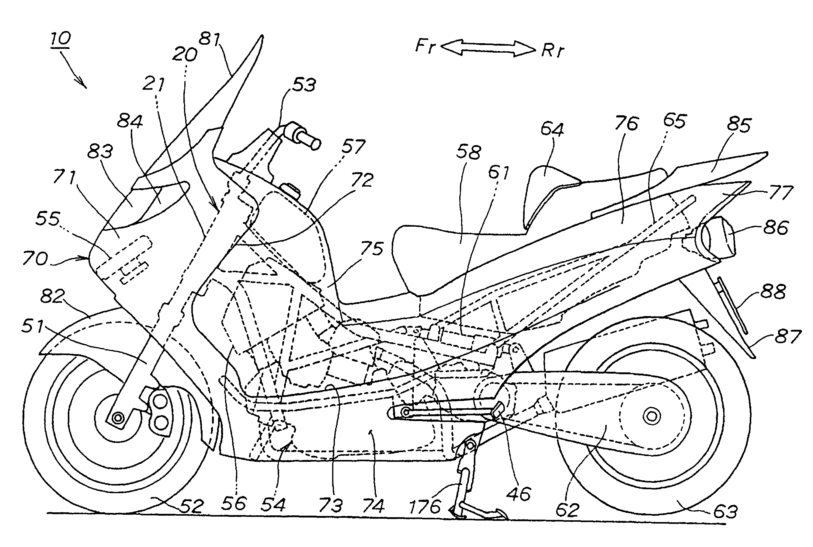
[0049]Referring to attached drawings, embodiments of the invention will be described below. “Front”, “rear”, “right”, “left”, “upper” and “lower” denote each position of a vehicle viewed from a rider, “Fr” means the front, “Rr” means the rear, “R” means the right, “L” means the left and “CL” means the center in the width of the body (the center of the body). The drawings shall be viewed with regard to the reference numbers.

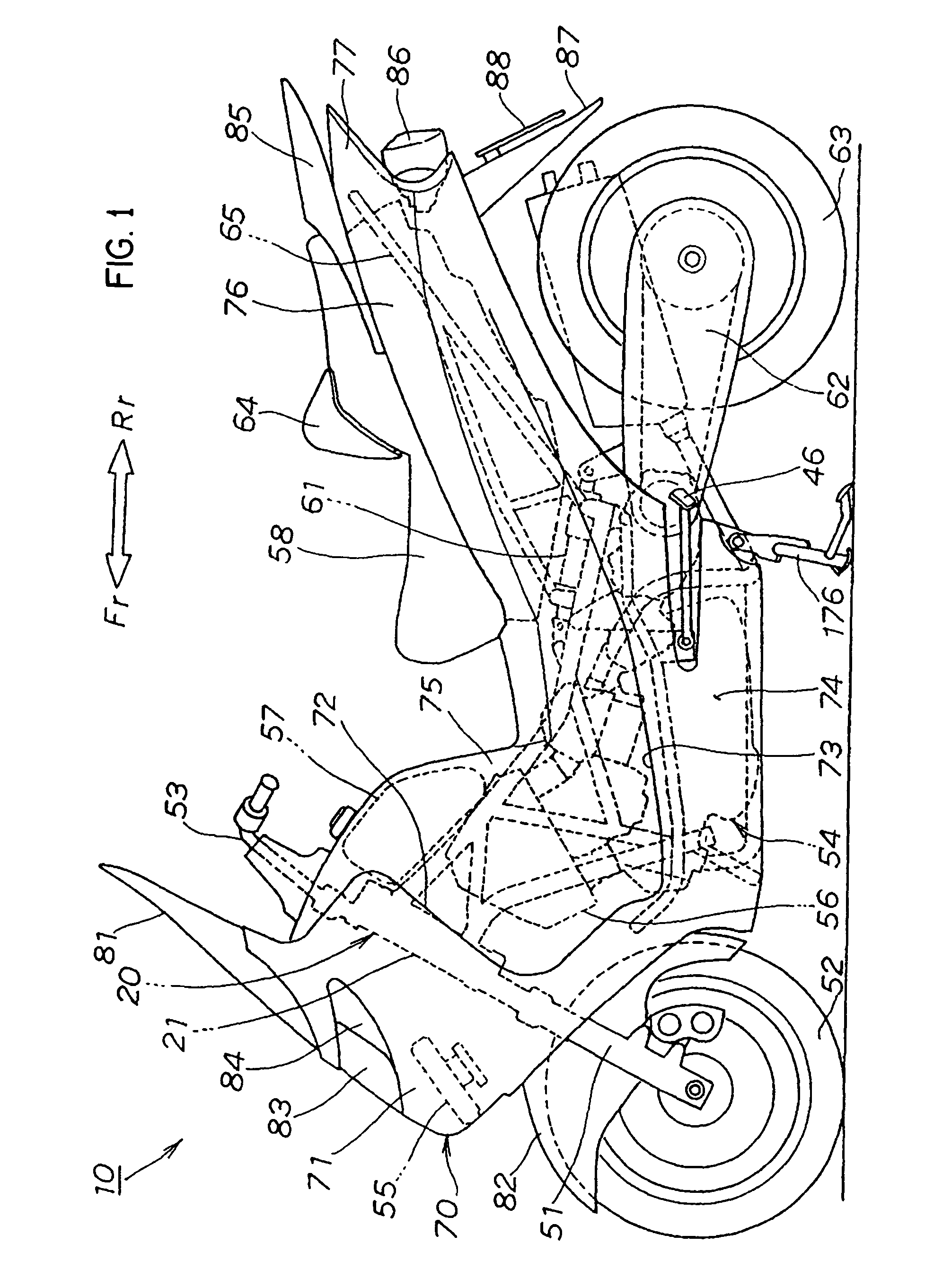
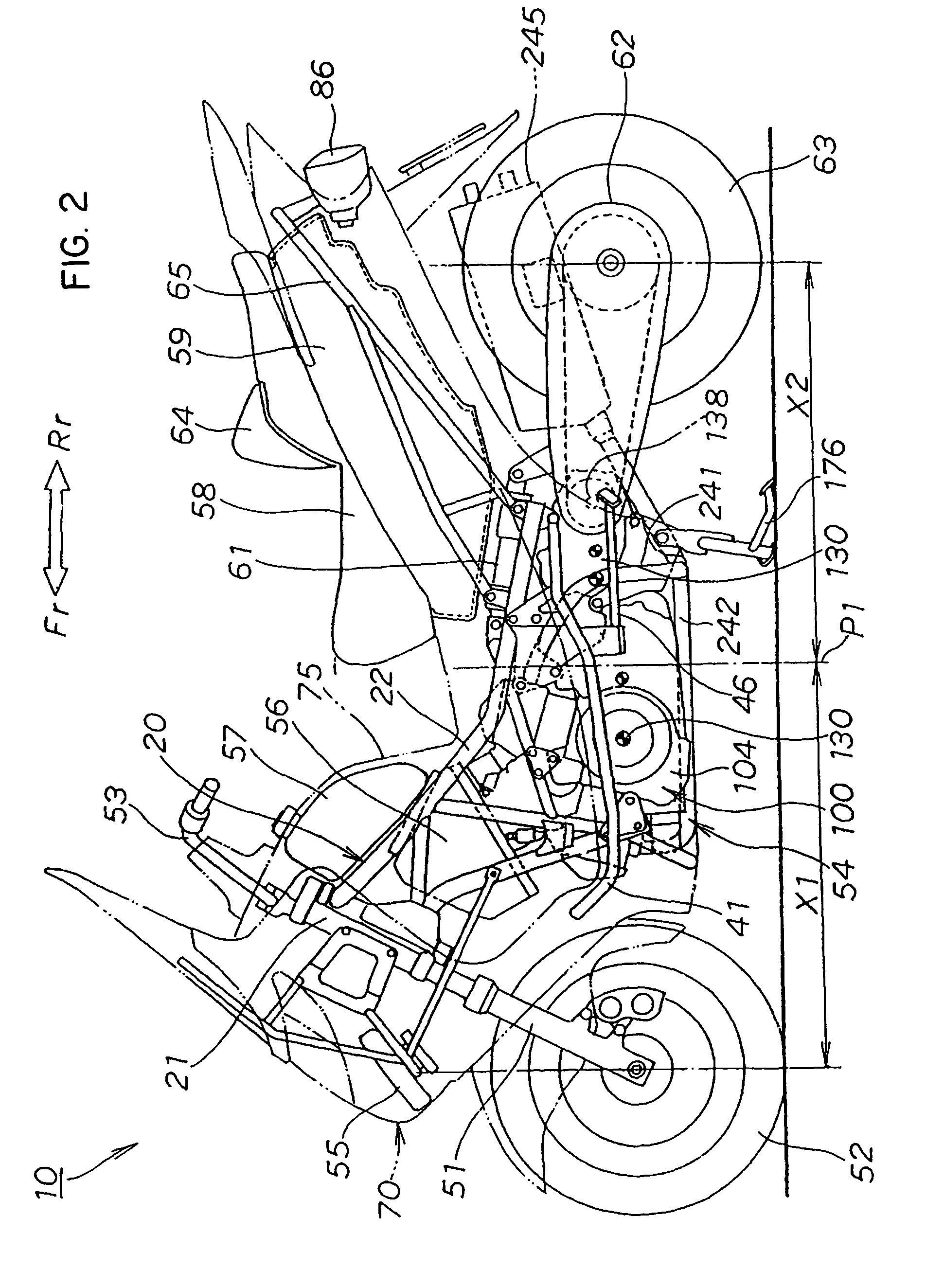
[0050]First, the whole configuration of a low floor type vehicle 10 will be described. FIG. 1 is a left side view showing the low floor type vehicle according to an embodiment of the invention and shows the configuration in which a body cover is attached. FIG. 2 is a second left side view showing the low floor type vehicle according to an embodiment of the invention and shows the configuration in which the body cover is detached. FIG. 3 is a top plan view showing the low floor type vehicle according to an embodiment of the invention and shows the configuration in ...


PUM


Abstract

A low floor type vehicle 10 is disclosed with a housing box 59 having substantially similar longitudinal length to the longitudinal length of a seat is provided under the seat 58 and a rear cushion for the rear wheel is transversely arranged under the housing box. The housing box is provided with a lid for checking the rear cushion for the rear wheel at the bottom. The engine is suspended from a diamond type frame 20. The rear cushion for the rear wheel is arranged along the rear of an upper frame extended backward and downward from a head pipe.

Description

FIELD OF THE INVENTION[0001]The present invention relates to a structure for improving the rear cushion installation structure of a low floor type vehicle.BACKGROUND OF THE INVENTION[0002]In a low floor type vehicle such as a scooter-type motorcycle or a scooter-type three-wheeled vehicle, a technique for mounting an engine below a body frame and arranging a rear cushion for a rear wheel substantially in the center of the body at the back of the engine is known (for example, Japanese published unexamined patent application No. 2001-88763 (see FIG. 2 on pp. 3 and 4)).[0003]FIG. 28 is a schematic diagram showing the conventional type low floor type vehicle of FIG. 2 of Japanese published unexamined patent application No. 2001-88763.[0004]A conventional type low floor type vehicle 300 is a scooter type motorcycle in which a power unit 320 is mounted in a double cradle type body frame under 310 and under a low floor 318.[0005]The body frame 310 is composed of a pair of right and left up...

Claims


Application Information

Patent Timeline
Patent Type & Authority Patents(United States)
IPC IPC(8): B62D25/24B62K11/04B62J9/00B62K11/00B62K25/00B62K25/20B62K25/28
CPCB62K25/00B62K25/283B62K2202/00B62K11/00
Inventor IIZUKA, CHIKASHITAKADA, YOSHIO
Owner HONDA MOTOR CO LTD
Why Eureka
Try Eureka