Grease gun

Active Publication Date: 2006-02-28
ALEMITE
View PDF42 Cites 43 Cited by
  • Summary
  • Abstract
  • Description
  • Claims
  • Application Information

AI Technical Summary

Benefits of technology

[0010]According to another aspect of the present invention, an air flow system is provided for a power tool housing defining an interior chamber and including a handle portion. The housing has at least one air inlet aperture in the handle portion and at least one air outlet aperture for placing the interior chamber in communication with the atmosphere. The air flow system comprises an electric motor adapted to be disposed in the handle portion of the housing. The motor comprises a motor housing having a first end wall, a second end wall and a body interconnecting the end walls. A fan is fixed to the drive shaft within the motor housing for drawing air through the motor housing. A wall integral with the handle portion of the housing extends inwardly into the interior chamber. The wall engages the body of the motor housing between the first end wall and openings in the body so that the interior chamber is divided into a first intake air portion, wherein the openings in the first end wall are in fluid communication with the atmosphere through the at least one air inlet aperture, and a second exhaust air portion, wherein the openings in the body and the second end wall are in fluid communication with the atmosphere through the at least one air outlet aperture. The wall provides a barrier to minimize air flow between the intake air portion of the interior chamber and the exhaust air portion. In use, the fan induces air flow from the intake air portion of the interior chamber into the motor housing through openings in the first end wall and from the exhaust air portion of the interior chamber into the motor housing through openings in the second end wall. Air is discharged from the openings in the body.
[0011]Also accor

Problems solved by technology

This requirement has led to the development of large, heavy power transmission mechanisms, resulting in awkward and difficult to handle grease guns.
The power requirement also reduces the life cycle of the rechargeable battery.
Moreover, since the transmission drive system includes numerous components, the manufacturing is relatively complicated and costly.
Another problem that affects all power tools, includin

Method used


Image

  • Grease gun
  • Grease gun
  • Grease gun

Examples


Example

[0025]Certain terminology is used herein for convenience only and is not to be taken as a limitation on the invention. For example, words such as “upper,”“lower,”“left,”“right,”“horizontal,”“vertical,”“upward,” and “downward” merely describe the configuration shown in the Figures. Indeed, the components may be oriented in any direction and the terminology, therefore, should be understood as encompassing such variations unless specified otherwise.

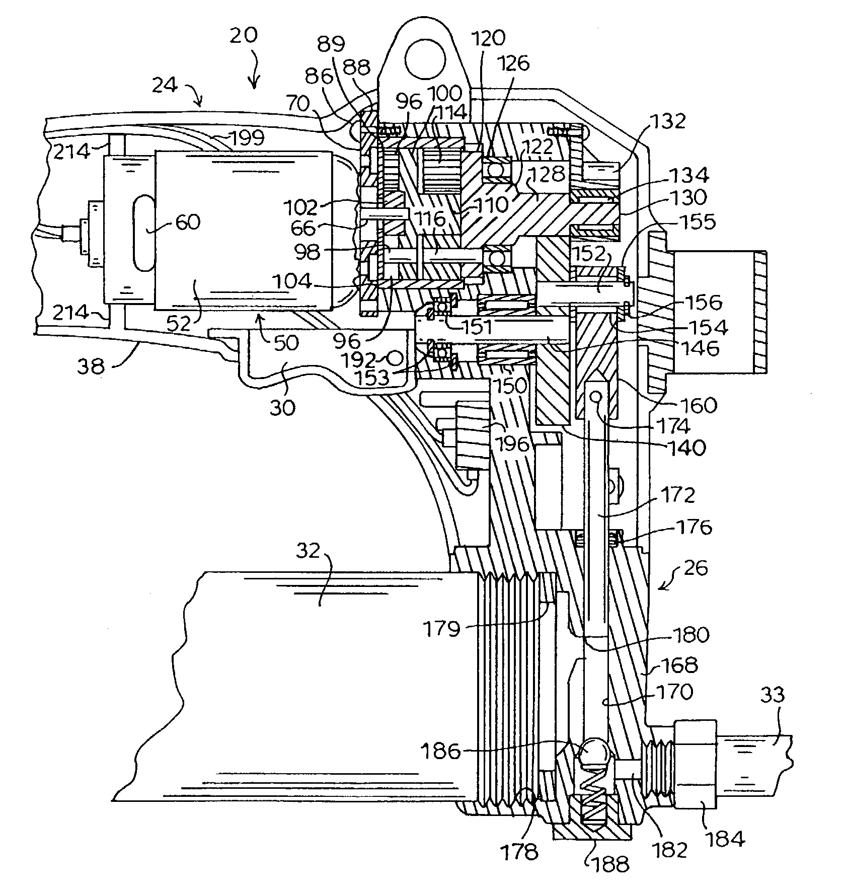
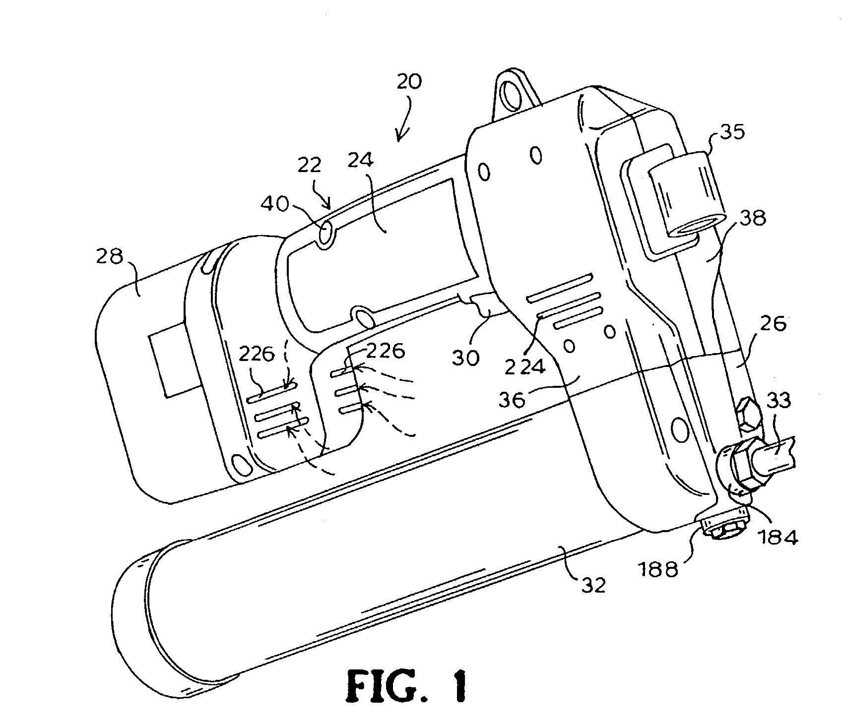
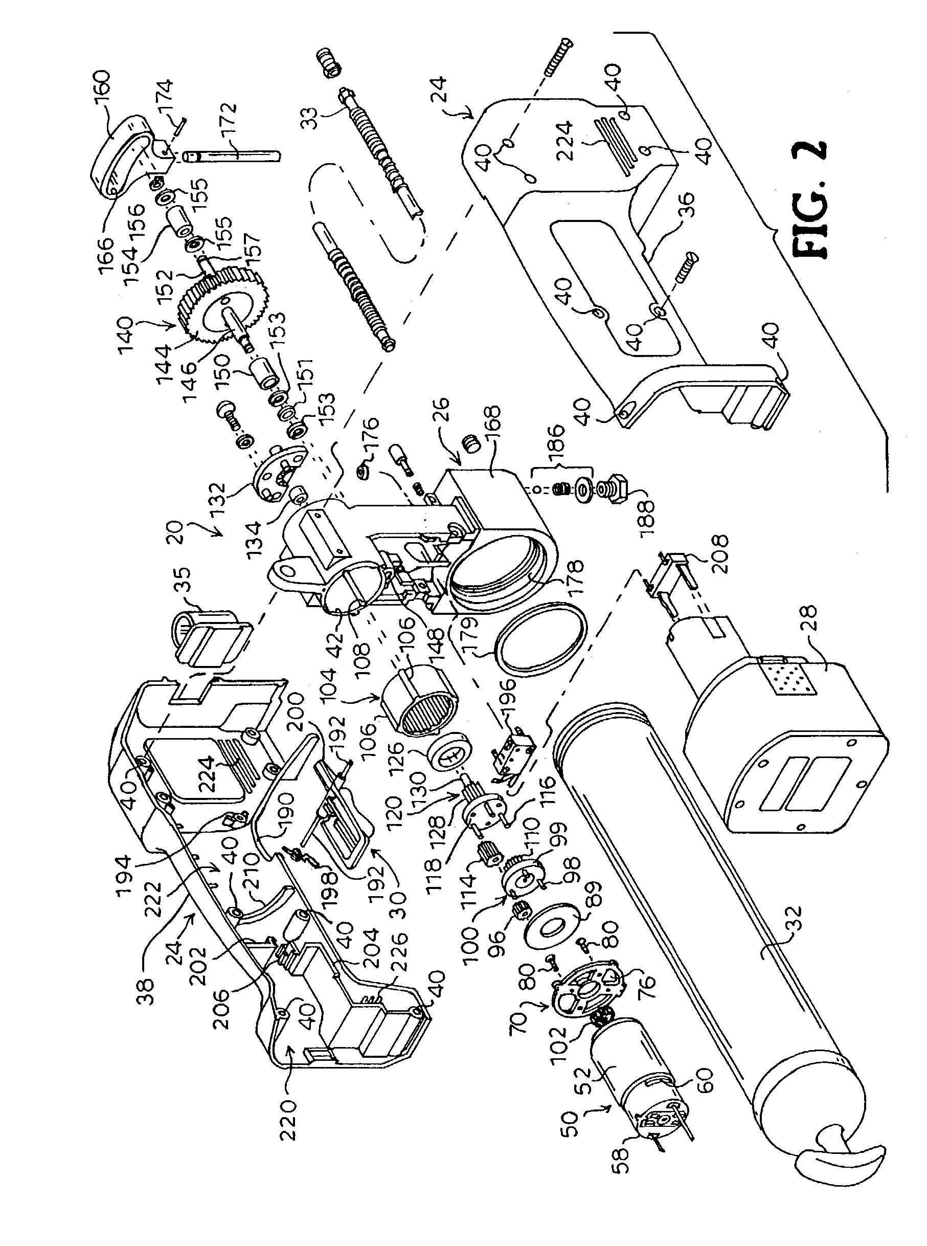
[0026]Referring now to the drawings, wherein like reference numerals designate corresponding or similar elements throughout the several views, an embodiment of the present invention is shown in the form of a battery-powered grease gun, designated generally at 20. It is understood that, although the present invention will be described in detail herein with reference to the exemplary embodiment of the battery-powered grease gun 20, the present invention may be applied to, and find utility in, other portable, hand-held power tools. As described...


PUM


Abstract

An apparatus converts rotary motion of a motor drive shaft into oscillatory motion of a work piece, for example, in a power tool. The apparatus comprises a planetary gear assembly connected to the motor for rotating an output gear. The output gear meshes with a drive gear including a drive pin. The drive pin fits in a yoke slot for reciprocation of the yoke upon rotation of the drive gear. The yoke is operatively connected to the work piece. An air flow system cools the power tool housing. The housing has an inlet aperture in the handle portion and an outlet aperture for placing the interior of the housing in communication with the atmosphere. A wall integral with the handle portion engages the body of the motor housing between a first end and openings in the body. The wall provides a barrier to minimize air flow between an intake air portion of the interior of the housing and an exhaust air portion. A fan on the motor drive shaft induces air flow from the intake air portion and exhaust air portion of the interior chamber into the motor housing through openings in the end walls. Air is discharged from the openings in the body.

Description

BACKGROUND OF INVENTION[0001]This invention generally relates to power tools and, more particularly, to portable, electrically-powered power tools, such as, for example, for pumping fluids as in a handheld battery-powered grease gun.[0002]A conventional handheld battery-powered grease gun generally comprises a housing including a head portion and a handle portion extending transversely from the head. A cylindrical barrel holding a supply of grease is removably secured to the head and extends from the head alongside the handle. The head portion includes a pump mechanism including a piston that reciprocates in a bore that forms a pump cylinder. The head portion has an inlet port in communication with the bore and the material in the barrel and an outlet port at one end of the bore to a flexible hose for delivering grease to a point of lubrication.[0003]An electric motor is accommodated in the housing and a gear transmission mechanism is provided between the motor and the pumping mecha...

Claims


Application Information

Patent Timeline
IPC IPC(8): G01F11/36G01F11/02
CPCF16N3/12G01F11/029G01F11/022F16N13/02Y10T74/1513Y10T74/18272B25F5/008
Inventor SHEW, JERRY D.
Owner ALEMITE
Why Eureka
Try Eureka