Dynamic bearing device, producing method thereof, and motor using the same

a bearing device and bearing technology, applied in sliding contact bearings, record information storage, instruments, etc., can solve problems such as potential decreases in adhesive strength, potential resonance problems, and potential decreases in press fitting strength

Active Publication Date: 2006-02-28
NIPPON DENSAN CORP
View PDF6 Cites 47 Cited by
  • Summary
  • Abstract
  • Description
  • Claims
  • Application Information

AI Technical Summary

Benefits of technology

[0036]According to this configuration, the lubricating oil filled in the internal space within the housing is able to circulate within the internal space, and as a result, the phenomenon wherein the pressure of the lubricating oil in the internal space is negative in localized areas can be prevented, enabling the solution of associated problems such as the generation of air bubbles accompanying the negative pressure generation, and the leakage of the lubricating oil or vibration arising from such air bubble generation.
[0037]Furthermore, in those cases where the bearing sleeve is secured to the inner peripheral surface of the housing with an adhesive, even if the go round of the adhesive occurs, since the recessed portion with the required capacity is provided between the outer diameter side region of the inside surface of the seal and the end surface at the end of the bearing sleeve, the adhesive is less likely to flow in the direction of the radial grooves. As a result, the situation in which the radial grooves become blocked with adhesive can be effectively avoided.

Problems solved by technology

However, accompanying the press fitting process, a predetermined region of the outer periphery of the housing undergoes expansion deformation outward, which might give rise to the following problems.
However, if during the press fitting of the thrust member, a portion of the bonding surface (securing surface) of the outer periphery of the housing undergoes expansion deformation, when securing the bearing device to the inner periphery of the retaining member, the gap in which the adhesive is filled becomes non-uniform in the axial direction, which leads to concerns over potential decreases in adhesive strength, and the potential occurrence of resonance problems.
Furthermore, securing the outer periphery of the housing closely to the inner periphery of the bracket (retaining member) via press fitting is another possibility, although in a similar manner to above, if during the press fitting of the thrust member, a portion of the press fitting surface (securing surface) of the outer periphery of the housing undergoes expansion deformation, when press fitting the bearing device to the inner periphery of the retaining member, the interference therebetween is non-uniform in an axial direction, which leads to concerns over potential decreases in the press fitting strength, and the potential occurrence of resonance problems.
Furthermore, when press fitting is employed as a means for securing the thrust member, the following problems might arise.
Any abrasion particles penetrating into the housing will invade the bearing portion among the lubricating oil to exercise an unfavorable influence on the performance or the life of the bearing.
However, depending on the quantity of adhesive that is applied, during the insertion of the bearing sleeve inside the housing and the movement of the bearing sleeve to the predetermined location, excess adhesive may go round to the front of the bearing sleeve as it moves to exercise an unfavorable influence on the positioning of the bearing sleeve or the performance of the bearing.
In this dynamic bearing device, however, the go round of the excess adhesive may cause the lateral grooves to be blocked with adhesive.

Method used


Image

  • Dynamic bearing device, producing method thereof, and motor using the same
  • Dynamic bearing device, producing method thereof, and motor using the same
  • Dynamic bearing device, producing method thereof, and motor using the same

Examples


Embodiment Construction

[0046]As follows is a description of embodiments of the present invention.

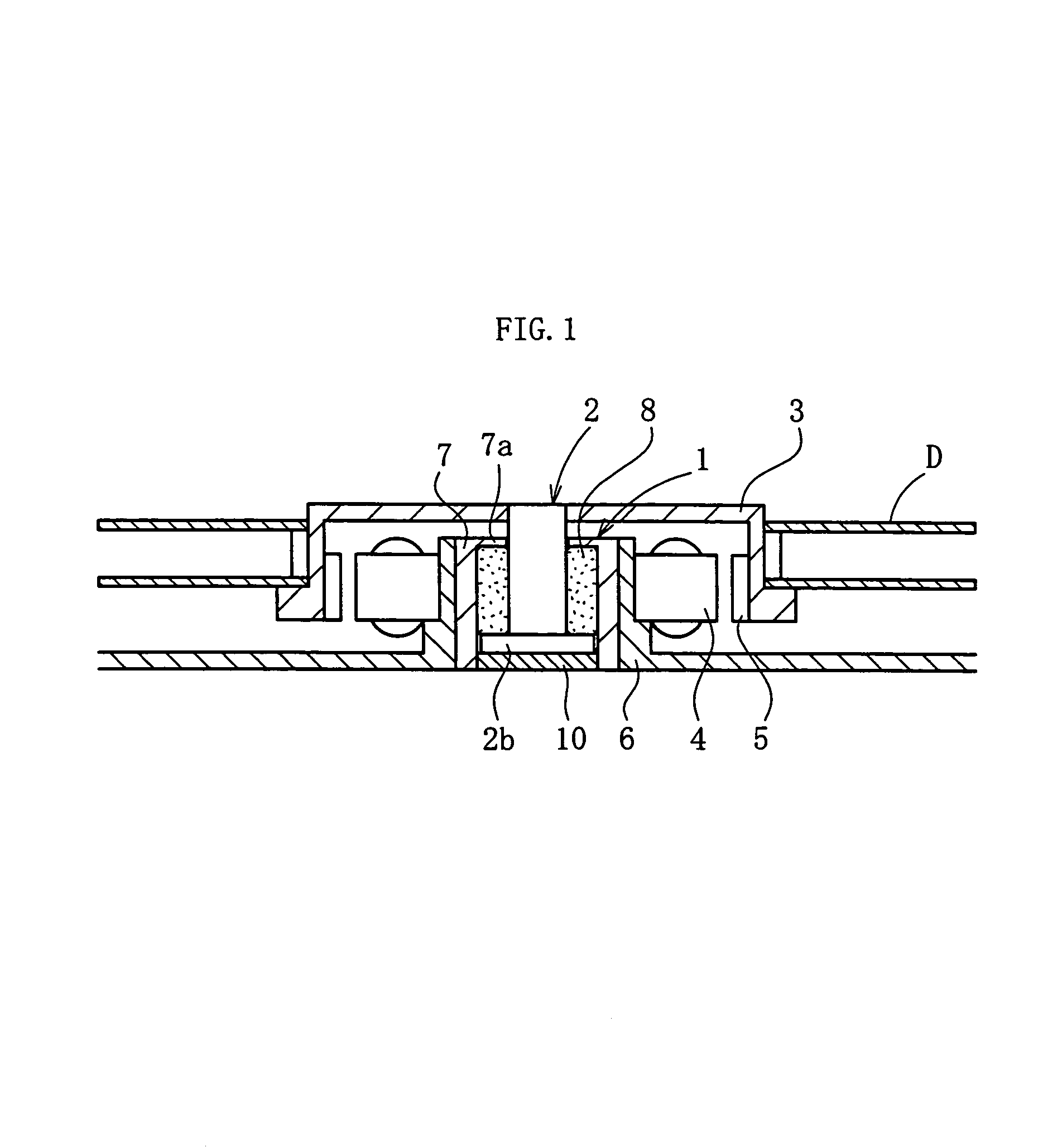
[0047]FIG. 1 shows one example of the construction of a spindle motor for information-processing equipment that incorporates a dynamic bearing device 1 according to the present embodiment. This spindle motor is used in a disk drive device such as HDD, and comprises a disk hub 3 serves as a rotor, a dynamic bearing device 1 for supporting the rotation of the disk hub 3, a bracket 6 serve as a retaining member for retaining the dynamic bearing device 1, and a stator 4 and a rotor magnet 5, which are provided between the disk hub 3 and the bracket 6, and oppose each other through a predetermined gap provided therebetween. In this embodiment, the disk hub 3 is mounted to an axial member 2 of the dynamic bearing device 1. The stator 4 is attached to the outer periphery of the bracket 6, the rotor magnet 5 is attached to the inner periphery of the disk hub 3, and the stator 4 and the rotor magnet 5 oppose each other...


PUM

PropertyMeasurementUnit
lengthaaaaaaaaaa
axial lengthaaaaaaaaaa
diameteraaaaaaaaaa

Abstract

A securing surface of a housing comprises a deformation region, which deforms radially outward by a predetermined quantity during press fitting of a thrust member, and another region. The deformation region has a tapered shape that gradually reduces in diameter in the downward direction, and is receded radially inward relative to the other region of the securing surface, by an amount equivalent to the amount of outward deformation thereof during press fitting. When the thrust member is press fitted into the inner periphery of a press fitting portion of the housing, the securing surface of the housing becomes substantially straight along entire axial region L thereof.

Description

BACKGROUND OF THE INVENTION[0001]1. Field of the Invention[0002]The present invention relates to a dynamic bearing device, which rotatably supports an axial member in a non-contact manner by an dynamic pressure action of a lubricating oil generated in a bearing gap, a producing method thereof, and a motor using the same. This bearing device is suitable for use in information-processing equipment, including the spindle motors for magnetic disk devices such as HDD and FDD, optical disk devices for CD-ROM, CD-R / RW, DVD-ROM / RAM, etc. and magneto-optical disk devices for MD, MO, etc., the polygon scanner motors in laser beam printers (LBP), or as small-scale motors for electrical equipment such as axial flow fans.[0003]2. Description of the Related Art[0004]In various types of the motor described above, performances such as increased speed, lower costs, and lower noise generation, in addition to high rotational precision, are required. One of the structural elements that determine these ...

Claims


Application Information

Patent Timeline
Patent Type & Authority Patents(United States)
IPC IPC(8): H02K5/12G11B17/02F16C17/02F16C17/04F16C17/26F16C33/10F16C33/74G11B19/20
CPCF16C17/02F16C17/04F16C17/107F16C33/107F16C33/74G11B19/2009F16C17/26F16C2370/12F16C33/104
Inventor TAMAOKA, TAKEHITOKURIMURA, TETSUYANAKAJIMA, RYOUICHI
Owner NIPPON DENSAN CORP
Why Eureka
Try Eureka