Temperature monitor for electro-mechanical part

Inactive Publication Date: 2006-02-28
SANYO ELECTRIC CO LTD
View PDF23 Cites 9 Cited by
  • Summary
  • Abstract
  • Description
  • Claims
  • Application Information

AI Technical Summary

Benefits of technology

[0010]According to the invention, a temperature recording device having a memory to store a temperature record based on measurements of temperature sensor is attached to an electric power-applied section, e.g., main circuit connection or high-voltage cable. This temperature recording device conducts a meas

Problems solved by technology

However, in the conventional temperature monitoring system using the thermo-sensing label, there is a problem that even when a periodical temperature change not reaching the extraordinary temperature occurs at the electric power-applied section due to an increase in amount of current carried, it cannot be detected since the system is desi

Method used


Image

  • Temperature monitor for electro-mechanical part
  • Temperature monitor for electro-mechanical part
  • Temperature monitor for electro-mechanical part

Examples


Example

[0024]Temperature monitoring system for electric power-applied section of the invention is explained below in reference to the drawings.

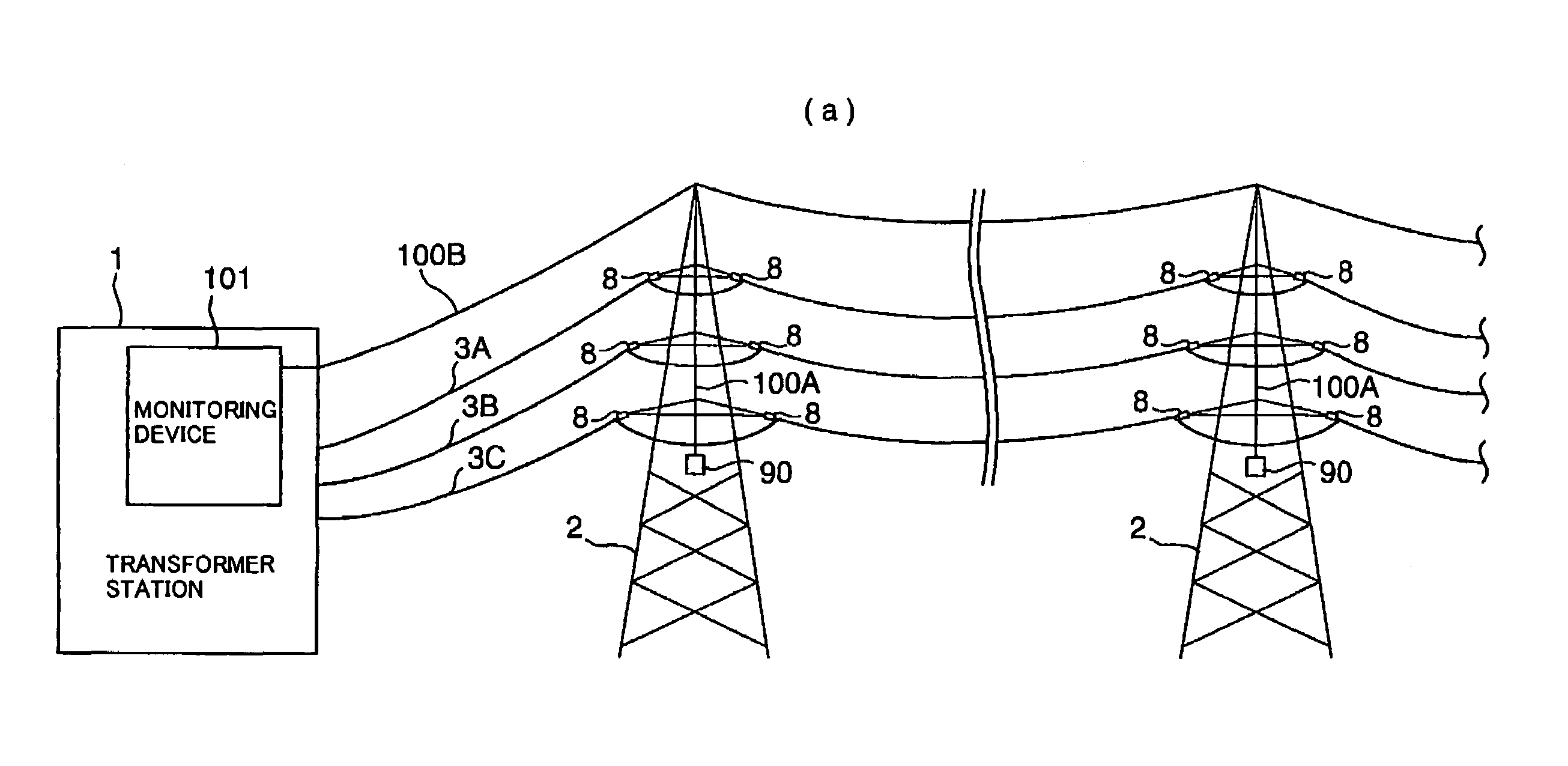
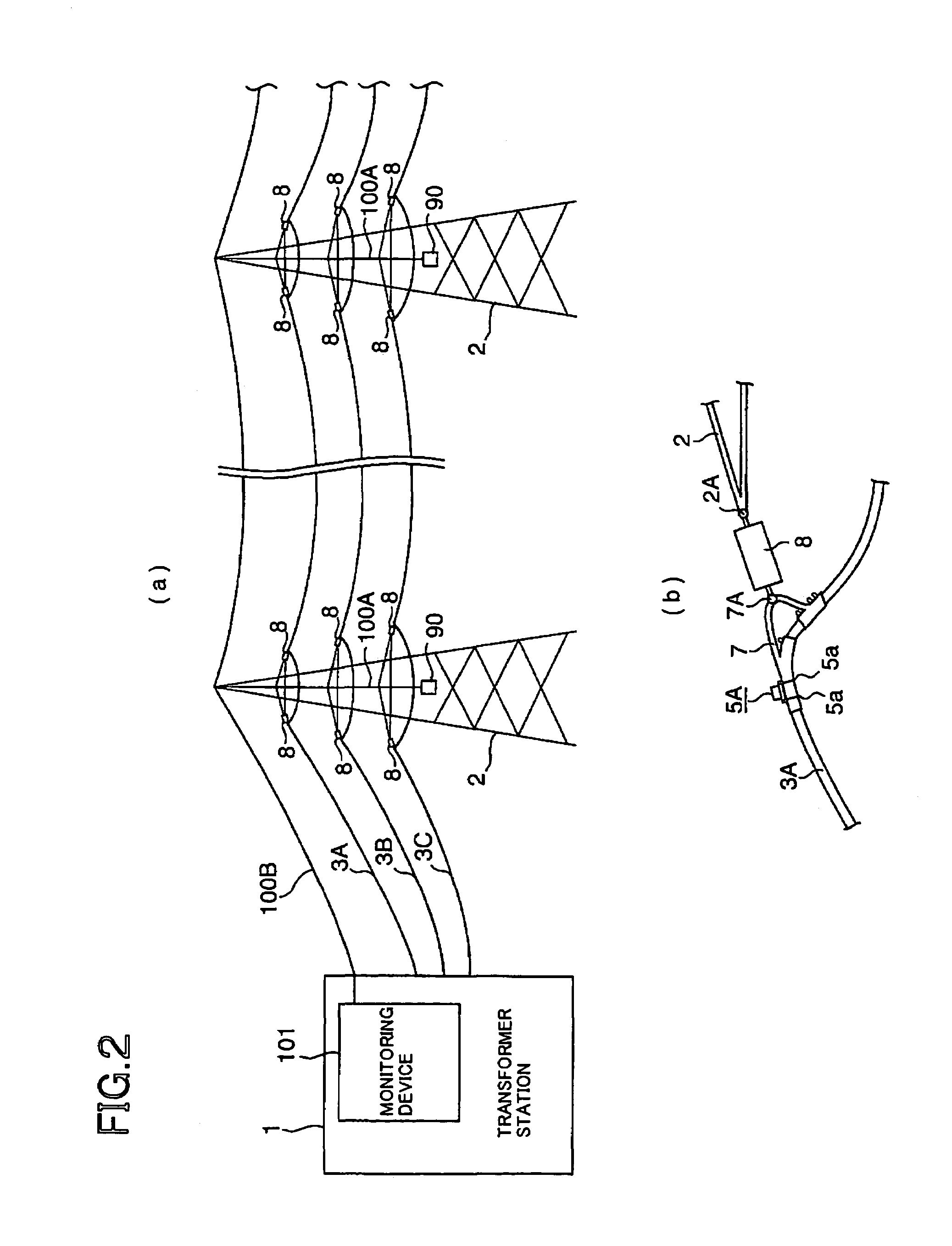
[0025]FIG. 2 shows an electric power-applied section in a preferred embodiment of the invention, FIG. 2(a) shows the schematic composition of a power transmission system, and FIG. 2(b) is an enlarged view showing a temperature monitor 5A installed on a power transmission line 3A. The power transmission system includes: a transformer station 1 that supplies electric power; power transmission lines 3A, 3B and 3C that are wired through a power transmission tower 2; an optical ground wire (OPGW) 100B, insulators 8 that suspend the power transmission lines 3A, 3B and 3C to the power transmission tower 2 while insulating them from the tower; temperature monitors 5A, 5B, 5C, 5D, 5E and 5F that are installed on the power transmission lines 3A, 3B and 3C to detect the temperature, recording it as a record of temperature history (hereinafter referred to as “t...


PUM


Abstract

A temperature monitor includes a temperature sensor, a transmitter, and a controller. The temperature sensor generates a temperature signal based upon a detected temperature and the controller controls the temperature sensor to generate the temperature signal and controls the transmitter to transmit the temperature signal along with a time at a first predetermined interval.

Description

[0001]This application is based on Japanese patent application No.2000-398294, the entire contents of which are incorporated herein by reference.TECHNICAL FIELD[0002]This invention relates to a temperature monitoring system for electric power-applied section and particularly to a temperature monitoring system for electric power-applied section that can safely and easily monitor the temperature change of electric power-applied section without incurring an accident such as electric shock.BACKGROUND ART[0003]Conventionally, to main circuit connection of transformer station and electric power-applied section of high-voltage cable, a thermo-sensing label is attached such that its color changes to indicate that a state of exceeding a predetermined temperature continues for a certain period for the purpose of constantly supplying electric power, thereby allowing the maintenance worker to visually monitor it.[0004]FIGS. 1(a) to (c) show a conventional structure for supporting the transmissi...

Claims


Application Information

Patent Timeline
IPC IPC(8): G08B17/00G01K1/02
CPCG01K1/024
Inventor KAWAI, SIGEKAZUKURIBARA, HIROYUKIISHIKURA, TSUTOMU
Owner SANYO ELECTRIC CO LTD
Why Eureka
Try Eureka