Side rail end connection system for bed frame

a technology of connecting system and bed frame, which is applied in the direction of bed, beds, fastening means, etc., can solve the problems of affecting the quality of bed frame, and unable to create a lasting solid connection, so as to achieve secure and tight connection

Active Publication Date: 2006-03-07
FINGER LAKES INTPROP
View PDF6 Cites 12 Cited by
  • Summary
  • Abstract
  • Description
  • Claims
  • Application Information

AI Technical Summary

Benefits of technology

[0010]Once the hooks have made an initial engagement with the pins, a lever arm that is pivotal affixed to the receiver housing can be rotated such that the lever arm contacts the upper surface of the metal hook plate forming the hooks and further rotation of the lever arm pushes downwardly on the metal hook plate to drive the forward edge of the slots and the pins together in a forceful engagement. With the downward movement of the hook plate brought about by the force of the lever arm on the hook plate, the receiver housing is drawn toward the hook plate to better and more firmly affix the side rail to the headboard or footboard.
[0011]Once the lever arm has reached a certain point of rotation, thereby creating sufficient downwardly directed force on the hook plate, there is a locking mechanism that secures and locks the lever arm in that locked position and such locking mechanism can be a spring located intermediate the lever arm and the hook plate having the hooks formed therein and that spring may be integrally formed with the lever arm or can be a separately attached spring component. The spring action creates an over the center arrangement that locks the lever arm in the desired position. The use of the spring is advantageous, since if the lever arm and a solid hook were used, due to the manufacturing tolerances, the lever arm might nest before it reaches its furthest or lowest position. As such the use of the spring action allows normal tolerances to be used in the construction of the mechanism and the handle will always be pushed down to its lowest, flush position.
[0012]Due to the steep angle of the forward edge of the slots, a lot of motion of the hook plate in the downward direction results in only slight inward movement of the receiver housing toward the side rail. This means that less downward force is required to produce a substantial compressive force drawing the pins and the hooks together and results in a very secure, tight connection therebetween. In addition, the weight of the bedding, including the box spring and mattress will add to the downward force to even better affix the side rail to the headboard or footboard. Thus, the more downward force on the hooks being forced against the pins, the more integral the connection becomes between the side rails and the headboard or footboard.

Problems solved by technology

There are disadvantages of both of these known systems.
With the bolt-on system, there is the difficulty in assembling a number of separate parts at a time and the need to utilize, and therefore require, a tool or tools to carryout the bolting procedure.
As to the hook and transverse pin system, the connection is subject to loosening and which can allow the headboard and footboard to rock and, therefore, not create a lasting solid connection.
In addition, with the use of hooks, if the user attempts to lift the bed frame by raising the side rails, those side rails will become disconnected as they lift out of the engagement with the headboard or footboard.

Method used


Image

  • Side rail end connection system for bed frame
  • Side rail end connection system for bed frame
  • Side rail end connection system for bed frame

Examples


Embodiment Construction

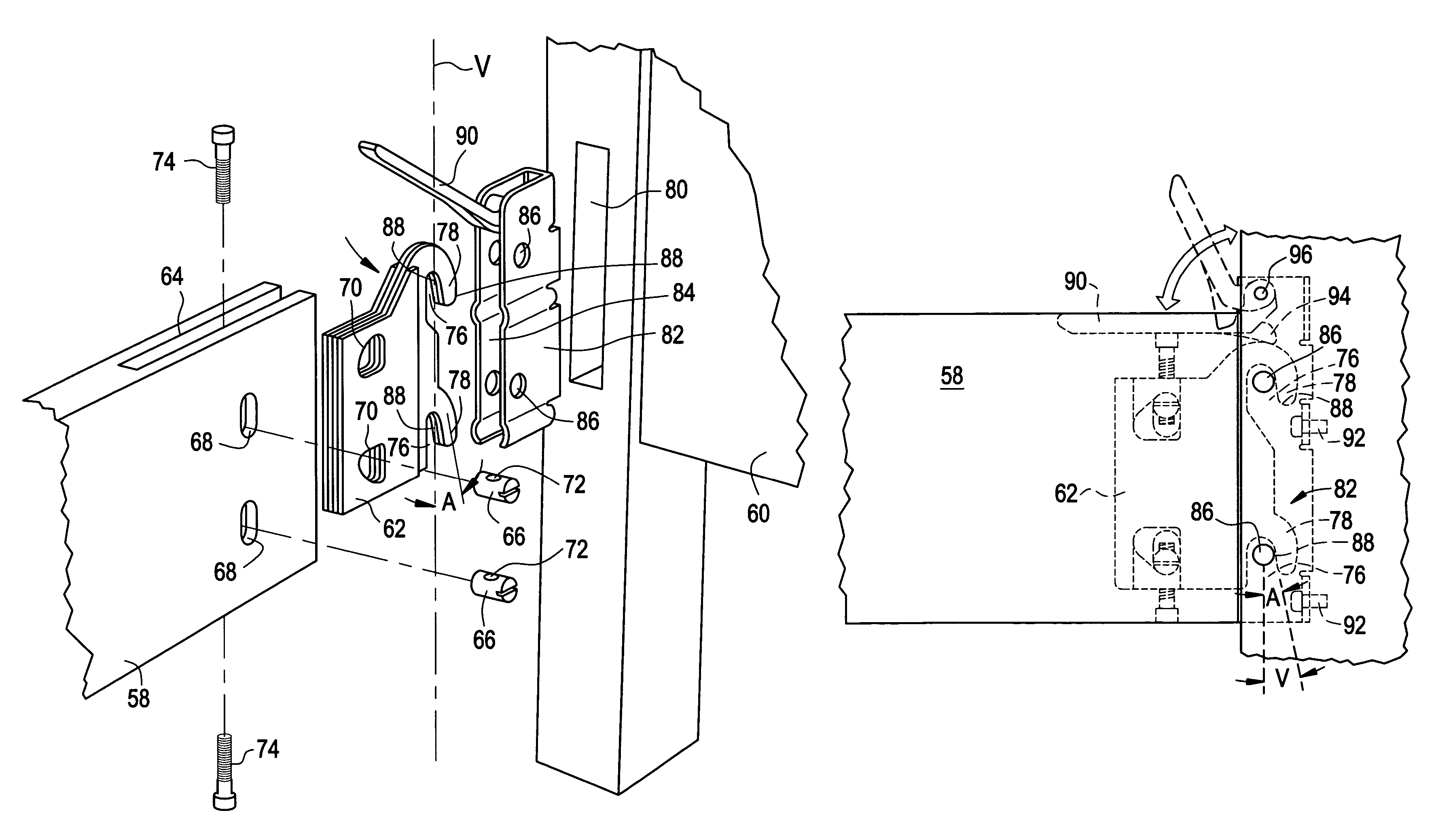
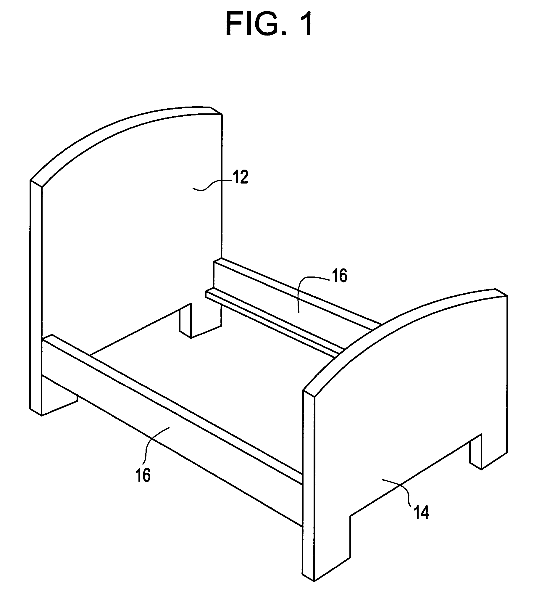
[0042]Referring now to FIG. 1, there is shown a perspective view of a bed frame and which comprises a headboard 12, a footboard 14 and a pair of side rails 16. The side rails are joined to the headboard 12 and footboard 14 so as to complete the bed frame. As can be seen, it is important that the junction between the side rails 16 and the headboard 12 and footboard 14 be a firm affixation so that the overall structure is solid and does not rock. The rocking motion between the various bed frame components contributes to the further loosening of the junctions so it is very important that each junction between the side rails 16 and the headboard 12 and footboard 14 be constructed so as to minimize the rocking effect.

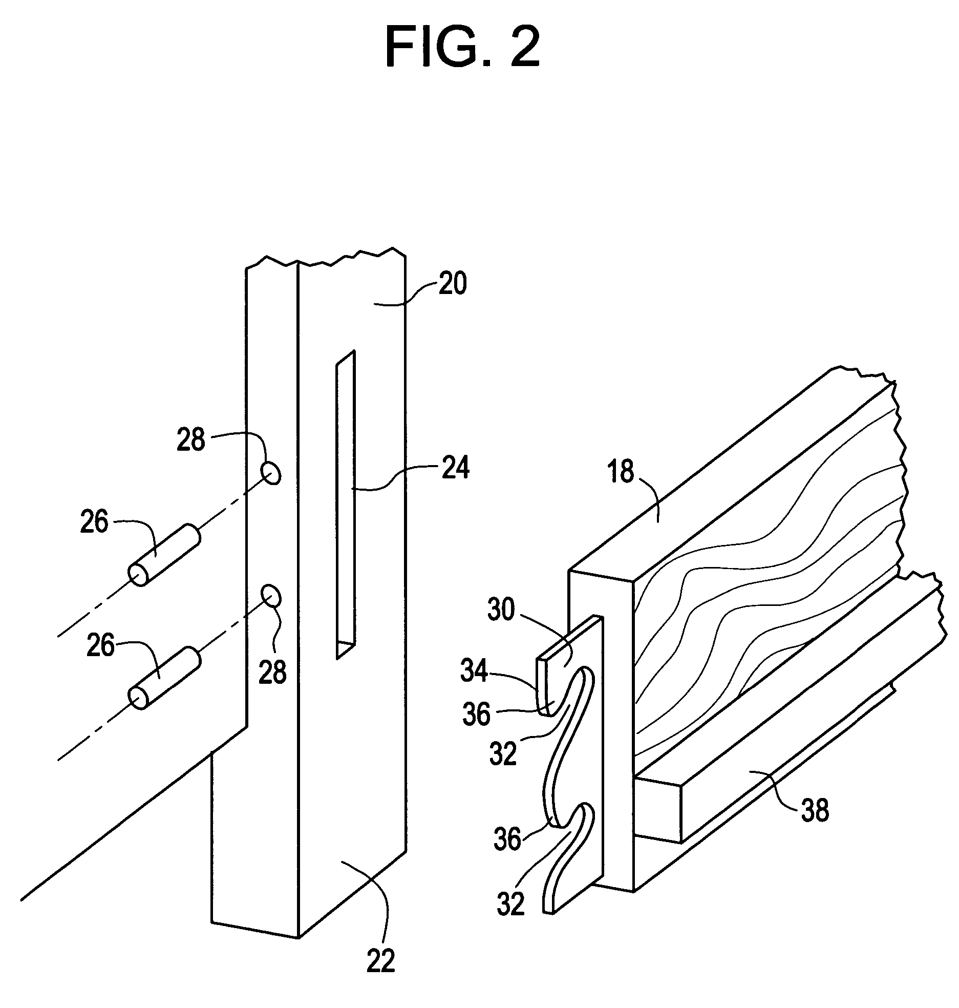
[0043]Accordingly, turning to FIG. 2, there is shown an exploded perspective view of a junction between a wooden side rail 18 and a headboard 20. In FIG. 2, it can be seen that the headboard 20 includes a vertical leg 22 that also serves as a main structural component of the...


PUM


Abstract

A system for connecting side rails of a bed frame with a headboard and / or footboard. A hook plate is affixed to the side rails and has a pair of hooks extending outwardly from the ends of the side rails. The hooks form slots in the hook plates and the slots have forward edges formed at a predetermined angle with respect to the vertical. A receiver housing is affixed to the headboard and / or footboard and has a vertical opening with a pair of transverse pins that span that opening. The side rails are affixed to the headboard and / or footboard by inserting the hooks into the vertical opening to engage the pins. A lever arm, pivotally affixed to the receiver housing, can be pivoted to force the hook plate downwardly to forcefully engage and lock the forward edge of the slots with the pins.

Description

CROSS-REFERENCE TO RELATED APPLICATIONS[0001]The present application is based upon U.S. Provisional patent application 60 / 524,136 filed Nov. 21, 2003 and entitled “SIDE RAIL END CONNECTION SYSTEM FOR BED FRAME”.BACKGROUND OF THE INVENTION[0002]The present invention relates to a bed frame construction and, more particularly, to a system used with a bed frame to attach the side rails to a headboard and / or a footboard.[0003]In general, a common bed frame system consists of a headboard and a footboard that are connected by two side rails that support the mattress and the box spring. While there may be differing ways to affix the side rails to the headboard and footboard, one of the most common is to bolt the side rails to the footboard and headboard or to assembly the side rail to the footboard and headboard with the use of a set of vertically space apart hooks that extend outward from the ends of the side rails and which enter vertically disposed slots formed in the headboard and footb...

Claims


Application Information

Patent Timeline
Patent Type & Authority Patents(United States)
IPC IPC(8): A47C19/02A47CA47C19/00A47C23/00
CPCA47C19/005F16B12/56F16B12/2009F16B12/02
Inventor POLEVOY, RICHARD S.RYAN, HOWARD SCOTTCARLSON, PAUL ERIC
Owner FINGER LAKES INTPROP
Why Eureka
Try Eureka