Wiper blade for cleaning panes of glass, particularly in motor vehicles

a technology for cleaning glass and blades, which is applied in the field of wiper blades, can solve the problems of affecting the effect of wiping and causing the vibrating of leaf springs

Inactive Publication Date: 2006-03-07
ROBERT BOSCH CORP
View PDF12 Cites 70 Cited by
  • Summary
  • Abstract
  • Description
  • Claims
  • Application Information

AI Technical Summary

Benefits of technology

[0004]To counteract chattering of the wiper blade of this generic type, it is embodied in accordance with the definitive features of the present invention. As a result, the structural height of the support element, which is low because of the support element can be kept low. The length of the wiper blade also remains limited to the minimum amount necessary for wiping.
[0005]If the mass body is embodied in striplike fashion and extends longitudinally of the support element, then depending on the applicable criteria it can be provided with a suitable length, which is at maximum approximately equivalent to the length of the wiper blade. In this way it is possible to adapt the available mass to requirements, without requiring greater space for the wiper blade.
[0012]In such embodiments of the wiper blade, it has proved especially advantageous if viewed in cross section, the extension of the wiper strip changes over, at the upper band side of the support element, into a bandlike base strip, with which the wiper strip is connected via an articulated strip formed by longitudinal grooves that are laterally open at the edges. The support element thus includes two spring bands, located in the same plane extending approximately parallel to the window, which rest in grooves assigned to them that are bounded at the top by the base strip. The spacing between the inner edges, oriented toward one another, of the spring bands makes it possible for the wiper strip to pass through support element. The articulated strip makes the requisite mobility of the mass body in the displacement direction of the wiper blade possible, and its dimensioning is oriented to the requirements in terms of the requisite vibration frequency of the mass body.

Problems solved by technology

Vibrations caused by the moment in the wiper arm and in the wiper blade—which causes the wiper blade to exert a so-called “stick-slip” effect on the window—also worsen the outcome of wiping.
If during the wiping work the wiper blade begins to chatter—which essentially leads to vibration in the plane of motion of the wiper blade—then the leaf spring is also induced to vibrate.

Method used


Image

  • Wiper blade for cleaning panes of glass, particularly in motor vehicles
  • Wiper blade for cleaning panes of glass, particularly in motor vehicles
  • Wiper blade for cleaning panes of glass, particularly in motor vehicles

Examples


Embodiment Construction

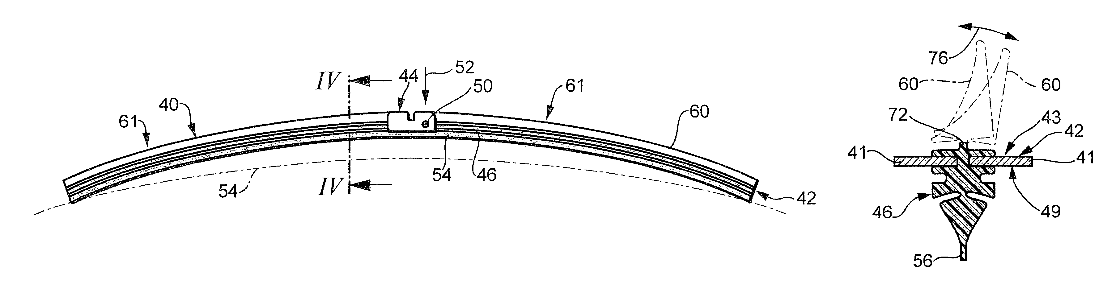
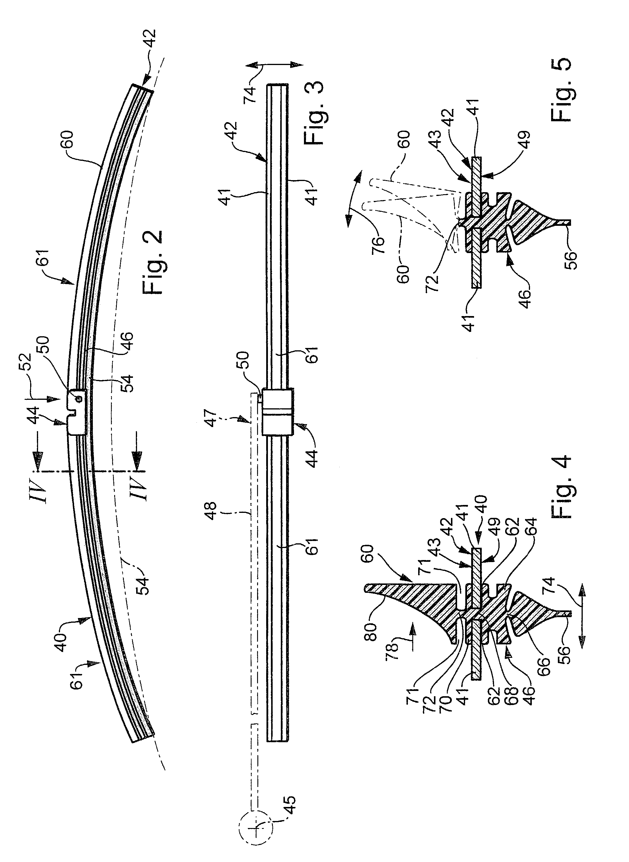
[0031]A wiper blade 40, shown in FIGS. 2 and 3, of a first embodiment of the invention has a bandlike-elongated, spring-elastic support element 42 with two spaced-apart, parallel spring rails 41 extending in the same plane. In the middle portion of the support element 42 (FIG. 4), on the top side 43 remote from the window 54 to be wiped, a connection device 44 is disposed, with the aid of which the wiper blade 40 can be connected releasably to a wiper arm 48 (FIGS. 2 and 3) driven in pendulum fashion about a pendulum axis 45 and guided on the body of a motor vehicle. An elongated, rubber-elastic wiper strip 46 is retained, longitudinally axially parallel, on the underside 49 of the support element 42, oriented toward the window 54. As a counterpart connection means, a pivot bolt 50 belonging to the connection device 44 of the wiper blade 40 is provided on the free end 47 of the wiper arm 48; it cooperates in the manner of a joint with a support point that is present in the connectio...


PUM


Abstract

A wiper blade is proposed which is used to clean windows, especially of motor vehicles. The wiper blade is displaceable transversely to its length, preferably about a pendulum axis, and can be pressed with an elongated, rubber-elastic wiper strip (46) against the window (54) to be wiped; the wiper strip is disposed on the lower band face (49), oriented toward the window, of a bandlike-elongated, spring-elastic support element (42). Chattering that occurs during wiping operation and causes an unsatisfactory outcome of wiping as well as considerable noise, is avoided if the region of the upper band face (43), remote from the window, of the support element (42), the wiper blade is provided with a mass body, which is disposed movably, at least in the displacement direction (74) of the wiper blade.

Description

BACKGROUND OF THE INVENTION[0001]In certain types of wiper blades, the support element is meant to assure the most uniform possible distribution, over the entire field swept by the wiper blade, of the wiper blade contact pressure, originating in the wiper arm, against the window. By means of a suitable curvature of the unstressed support element—that is, when the wiper blade is not resting on the window—the ends of the wiper strip, which in wiper blade operation presses completely against the window, are stressed toward the window by the then-tensed support element, even if the radii of curvature of spherically curved vehicle windows change at every position of the wiper blade. The curvature of the wiper blade must accordingly be somewhat greater than that in the swept field, at the most pronounced measured curvature of the window to be wiped. The support element thus replaces the known, complicated support bracket construction with two spring rails disposed in the wiper strip and s...

Claims


Application Information

Patent Timeline
Patent Type & Authority Patents(United States)
IPC IPC(8): B60S1/38
CPCB60S1/3808B60S1/3879B60S2001/3812
Inventor WEILER, MICHAELZIMMER, JOACHIM
Owner ROBERT BOSCH CORP
Why Eureka
Try Eureka