Method and system of controlling a work tool

a technology of work tools and control methods, applied in the direction of process and machine control, vehicle position/course/altitude control, instruments, etc., can solve the problems of reducing the efficiency of the work machine, difficult to closely follow the boundary surfaces of the work machine with the work implement assembly, and often complex process of excavating a work site with a work machine to obtain a desired configuration

Inactive Publication Date: 2006-03-07
CATERPILLAR INC
View PDF16 Cites 31 Cited by
  • Summary
  • Abstract
  • Description
  • Claims
  • Application Information

AI Technical Summary

Problems solved by technology

Excavating a work site with a work machine to obtain a desired configuration can often be a complex process.
Depending on the nature of the excavation, closely following these boundary surfaces with a work implement assembly of the work machine can be difficult.
Although useful in ensuring that the work implement assembly does not pass beyond a pre-designated limit, prior art work machines including a control system as described in the '604 patent may reduce the efficiency of the work machine when the work tool is operating near the pre-designated limit.
Accordingly, these types of control systems may interrupt the work of the operator and prevent the work tool from moving easily along the limit position or boundary.

Method used


Image

  • Method and system of controlling a work tool
  • Method and system of controlling a work tool
  • Method and system of controlling a work tool

Examples


Embodiment Construction

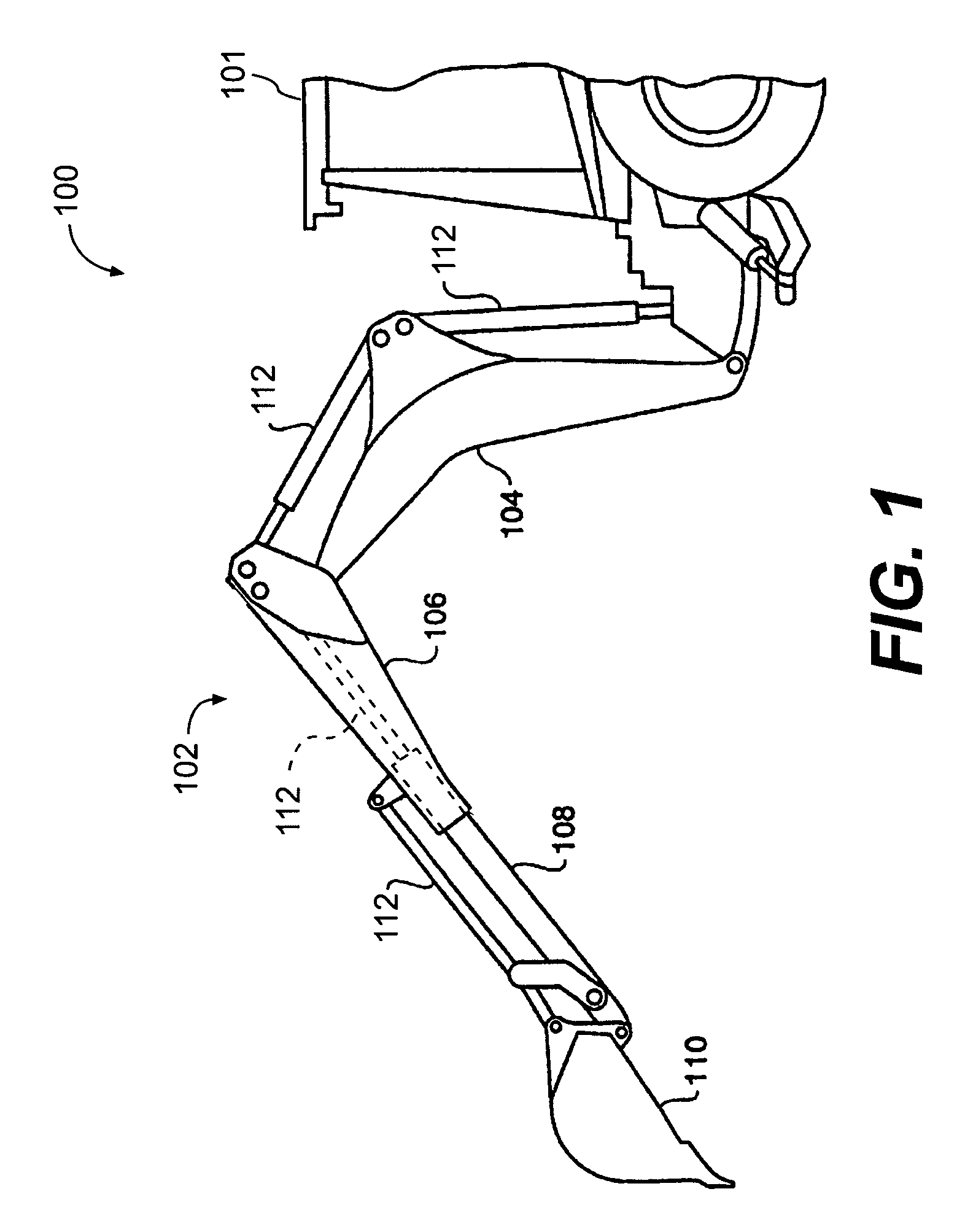
[0013]FIG. 1 illustrates an exemplary embodiment of a relevant portion of a work machine 100. The work machine 100 may be used for a wide variety of earth-working and construction applications. Although the work machine 100 is shown as a backhoe loader, it is noted that other types of work machines 100, e.g., excavators, front shovels, material handlers, and the like, may be used with embodiments of the disclosed system.

[0014]The work machine 100 includes a body 101 and work implement assembly 102 having a number of components, including, for example, a boom 104, a stick 106, an extendable stick (E-stick) 108, and a work tool 110, all controllably attached to the work machine 100. The boom 104 is pivotally connected to the body 101, the stick 106 is pivotally attached to the boom 104, the E-stick 108 is slidably associated with the stick 106, and the work tool 110 is pivotally attached to the E-stick 108, as is known in the art. The work implement assembly 102 may pivot relative to ...


PUM


Abstract

A method for controlling movement of a work tool includes the step of identifying a predefined digging boundary and determining the current position of the work tool. A control signal is generated to change the position of the work tool. A requested motion vector is determined for the work tool based on the control signal. A determined force is generated to apply to the work tool. It is based on the requested motion vector and has a normal component that is scaled to prevent the work tool from crossing the predefined digging boundary. One aspect is directed to a control system for a work tool on a work implement assembly.

Description

TECHNICAL FIELD[0001]This invention relates to a system and method for controlling the movement of a work tool and, more particularly to a system and method for controlling movement of the work tool along a predefined digging boundary.BACKGROUND[0002]Excavating a work site with a work machine to obtain a desired configuration can often be a complex process. The desired surface configuration may include a boundary surface having, for example, symmetric or non-symmetric walls, floors, ramps, or curves. An operator may control the motion of the work machine to carve out the volume defined by the boundary surfaces. Depending on the nature of the excavation, closely following these boundary surfaces with a work implement assembly of the work machine can be difficult. Accordingly, it takes a skilled operator to be able to successfully and accurately dig out an excavation having such boundary surfaces.[0003]Some work machines have a computer system that is capable of storing the desired bo...

Claims


Application Information

Patent Timeline
Patent Type & Authority Patents(United States)
IPC IPC(8): G05D1/10E02F3/43
CPCE02F3/437
Inventor KOCH, ROGER D.
Owner CATERPILLAR INC
Why Eureka
Try Eureka