
Thermal management system for a vehicle

a technology of management system and vehicle, applied in the direction of lighting and heating apparatus, heating types, domestic cooling apparatus, etc., can solve the problems of uneven or undesired noise levels, extended idle may have negative effects on engine life, and inefficient use of engine for a long tim

Inactive Publication Date: 2006-03-07
CATERPILLAR INC
View PDF9 Cites 67 Cited by
  • Summary
  • Abstract
  • Description
  • Claims
  • Application Information

AI Technical Summary

Benefits of technology

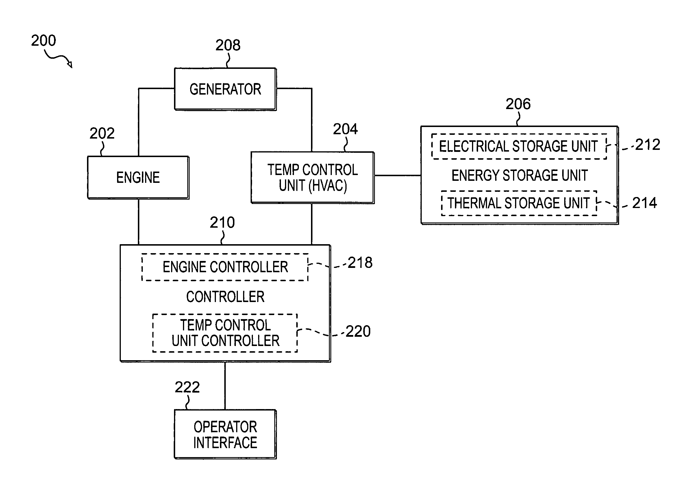
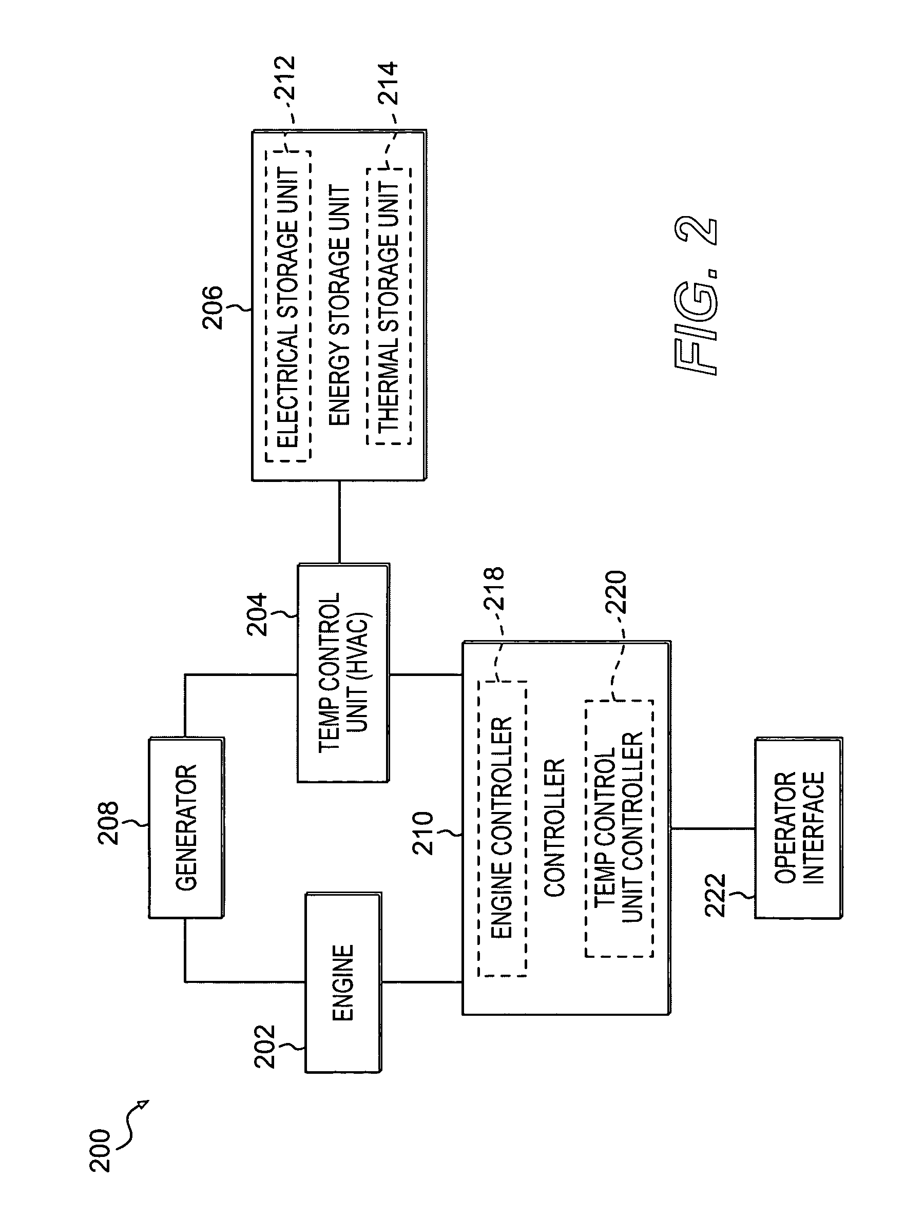
The present patent is about a system and method for managing the temperature of a vehicle using an engine and an energy storage unit. The system includes a controller that monitors the operating condition of the system and controls the transfer of energy from the engine to the storage unit based on the monitored condition. This allows for efficient management of the vehicle's temperature even when the engine is not operating. The technical effect of this patent is to provide a more efficient and effective way to manage the temperature of a vehicle.

Problems solved by technology

To idle such an engine for an extended period of time is an inefficient use of the engine and a waste of fuel.
They may vibrate and cause uneven or undesired noise levels while idling.
Additionally, extended idling may have negative effects on engine life.
Recognizing that the practice of idling while resting results in inefficient fuel consumption and additional emissions from the engine into the air, federal and state governments, along with industry, are looking for a solution to reduce truck idling during resting.
Such a system, although an improvement over the prior art, still has many drawbacks.
For example, as the energy level in the battery decreases, the HVAC may no longer be able to operate.
Furthermore, such a system may direct energy generated by the engine to a recharger instead of providing the maximum amount of energy for driving the truck such as, for example, when a truck is going uphill and needs the maximum amount of energy.

Method used


Image

  • Thermal management system for a vehicle
  • Thermal management system for a vehicle
  • Thermal management system for a vehicle

Examples


Embodiment Construction

[0017]Reference will now be made in detail to embodiments of the present invention, examples of which are illustrated in the accompanying drawings. Wherever possible, the same reference numbers will be used throughout the drawings to refer to the same or like parts.

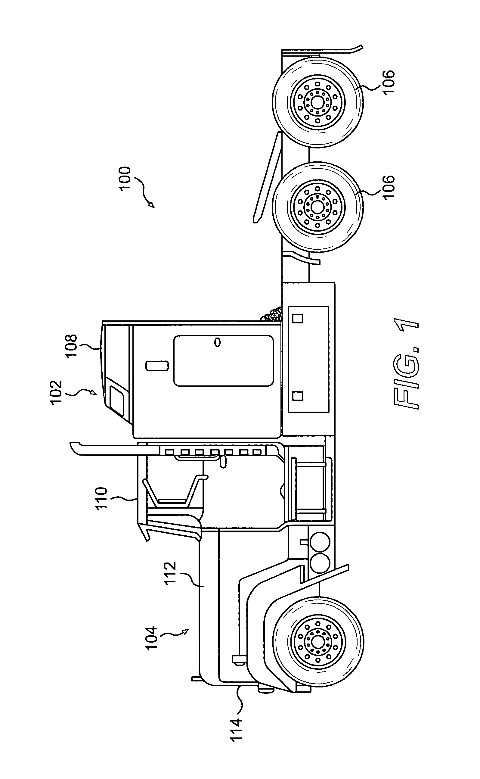
[0018]An exemplary embodiment of a vehicle 100 is illustrated in FIG. 1. The vehicle 100 may be an on-highway truck, an off-highway truck, or other vehicle. In the exemplary embodiment shown, the vehicle 100 includes an operator compartment 102, a propulsion system housing 104, and driving wheels 106. The operator compartment 102 may include a cabin 108 and a cab 110. The cabin 108 may be used as resting quarters for an operator of the vehicle 100. It may include a bed and / or other accommodations, as is known in the art. The cab 110 may be used by an operator when driving the vehicle 100.

[0019]The propulsion system housing 104 may include a hood 112 and a grill 114. An engine and / or other driving components may be contain...


PUM


Abstract

A thermal management system for a vehicle includes an engine operable to generate energy. An energy storage unit may be associated with the engine and adapted to receive and store the energy generated by the engine. A temperature control unit may be associated with the energy storage unit and adapted to control a temperature in the vehicle. The temperature control unit may be adapted to selectively draw stored energy from the energy storage unit to control the temperature when the engine is not operating. A controller may be adapted to monitor an operating condition of the thermal management system and to control the transfer of the energy from the engine to the energy storage unit based on the monitored operating condition.

Description

[0001]This invention was developed with government support under U.S. Government Contract No. DE-FC04-2000AL67017. Accordingly, the U.S. Government has certain rights to this invention.TECHNICAL FIELD[0002]This invention relates generally to a thermal management system, and more particularly to a thermal management system for a vehicle.BACKGROUND[0003]Truck drivers spend about 1800 hours per year resting in their cabs. In order to provide an environment suitable for resting and sleeping, the cabs are provided with heating and / or air conditioning units. Typically, drivers idle their truck engines while resting to provide power to operate the heating and air conditioning units. To idle such an engine for an extended period of time is an inefficient use of the engine and a waste of fuel.[0004]For example, a typical on-highway truck burns approximately 0.6 to 0.9 gallons per hour while idling. Accordingly, fuel consumed during idling could be within the range of 1665 gallons per year. F...

Claims


Application Information

Patent Timeline
Patent Type & Authority Patents(United States)
IPC IPC(8): F25B1/00F25B27/00F25B49/00B60H1/00B60H1/02F25D11/00
CPCB60H1/00492B60H1/00378
Inventor GRIMM, MARK THOMASMCENANEY, RYAN PATRICK
Owner CATERPILLAR INC
Learn More