Device for reducing vehicle aerodynamic resistance

a technology for which is applied in the direction of roofs, transportation and packaging, vehicle arrangements, etc., can solve the problems of reducing saving fuel, and streamlining the front of the rectangular vehicle such as the semi trailer is impractical, so as to reduce the aerodynamic resistance of the moving vehicle

Active Publication Date: 2006-03-07
FREIGHT WING
View PDF22 Cites 126 Cited by
  • Summary
  • Abstract
  • Description
  • Claims
  • Application Information

AI Technical Summary

Benefits of technology

[0004]In general, a device for reducing vehicle aerodynamic resistance disposed on the front of a movable vehicle with a generally flat front face, when made in accordance with this invention, comprises a plurality of load bearing struts of a predetermined size fastened to the flat front face adjacent the sides and top thereof. A pair of opposing sheets of flat pliable material each of which have an outside edge portion that is attached to opposite sides of the flat front face, an inside edge portion attached to adjacent struts and a prede

Problems solved by technology

It is well known that streamlining the front of a vehicle such as a trailer truck will reduce the aerodynamic resistance of a moving vehicle and thus save fuel.
However, streamlining the front of a rectangular vehicle such as a semi trailer is impractical because the cargo space inside is decreased.
However, past desi

Method used


Image

  • Device for reducing vehicle aerodynamic resistance
  • Device for reducing vehicle aerodynamic resistance
  • Device for reducing vehicle aerodynamic resistance

Examples


Embodiment Construction

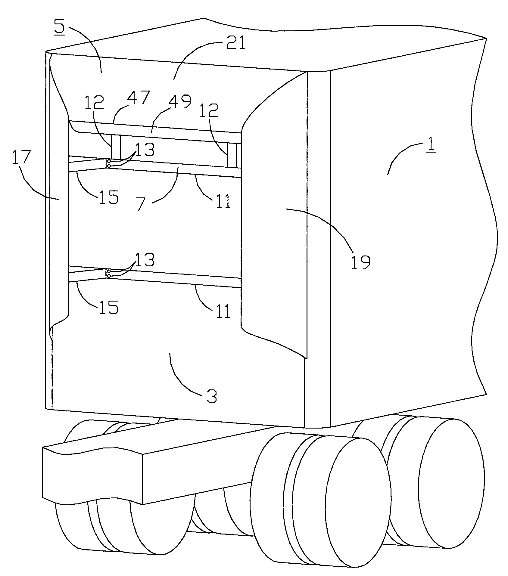
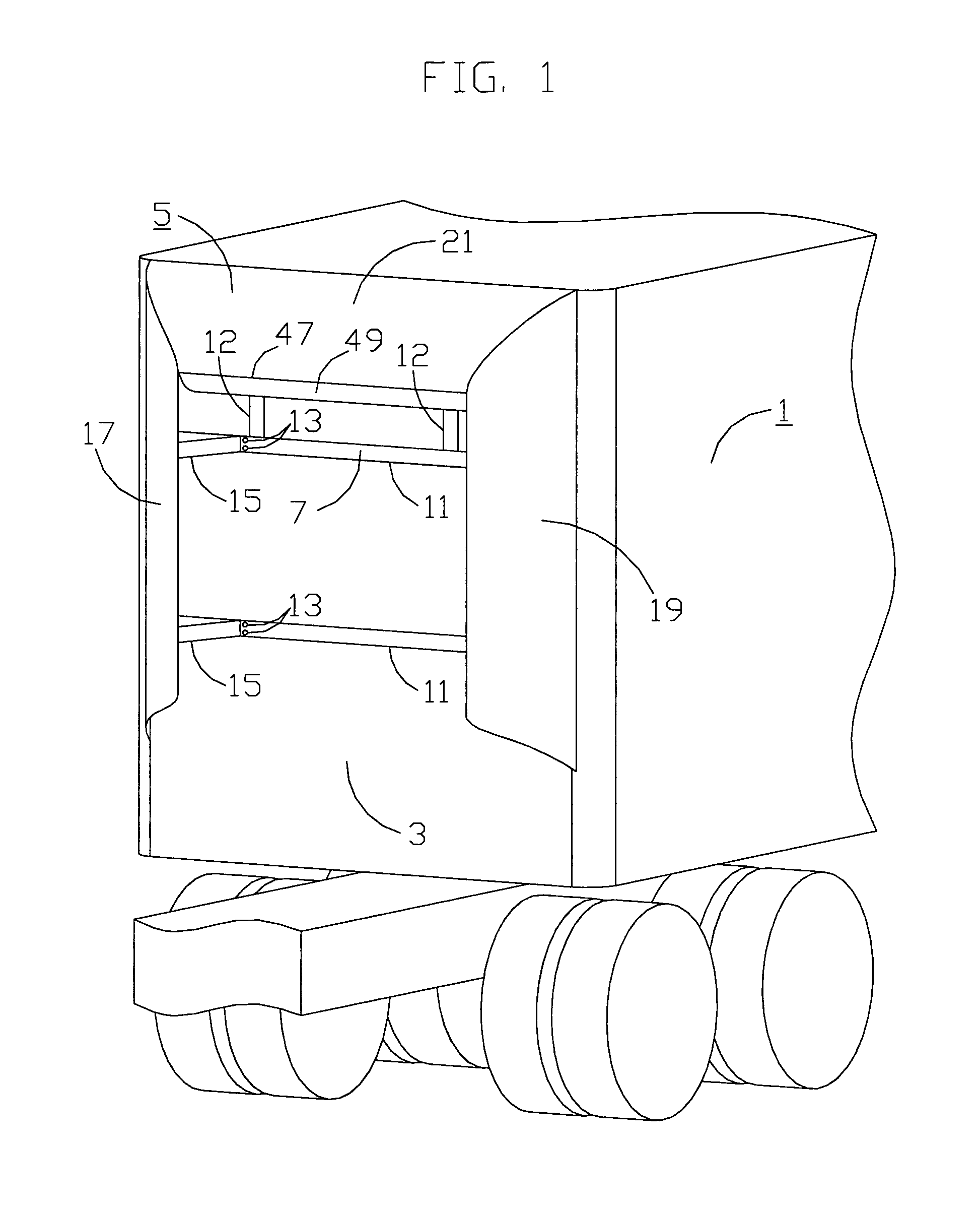
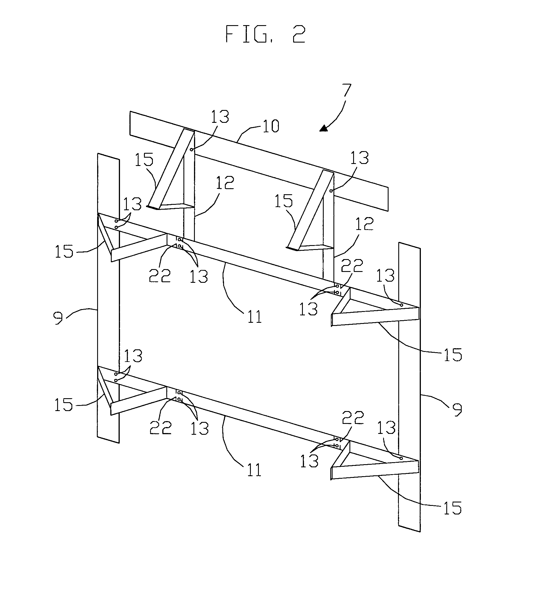
[0016]Referring now to the drawings in detail and in particular to FIG. 1, there is shown a vehicle 1 such as a trailer truck, having a generally rectangular flat front face 3 and an effective airfoil device 5 for reducing the aerodynamic resistance of the vehicle 1 when it moves fastened to the flat front face 3. The device 5 comprises a frame 7 having a plurality of parallel cross members 11 and a plurality of vertical cross members 12. The parallel cross members 11 are fastened to the flat front face 3 by rivets 13 or other fastening means. Load bearing struts 15 are fastened to the parallel cross members 11 and vertical cross members 12. Opposing flat sheets 17 and 19 of pliable material are fastened to the frame 7 and bent to form curved airfoil shapes and fastened to the load bearing struts 15 to form the sides of the effective airfoil device 5. A top flat sheet 21 of pliable material is fastened to the frame 7 and bent to form a curved airfoil shape and fastened to load beari...


PUM


Abstract

A device for reducing vehicle aerodynamic resistance for vehicles having a generally rectangular flat front face comprising a plurality of load bearing struts of a predetermined size attached to the flat front face adjacent the sides and top thereof, a pair of pliable opposing flat sheets having an outside edge portion attached to the flat front face adjacent the sides thereof and an upper edge with a predetermined curve; the opposing flat sheets being bent and attached to the struts to form effective curved airfoil shapes, and a top pliable flat sheet disposed adjacent the top of the flat front face and having predetermined curved side edges, which, when the top sheet is bent and attached to the struts to form an effective curved airfoil shape, mate with the curved upper edges of the opposing sheets to complete the aerodynamic device.

Description

[0001]This invention was made with Government support under Contract No. DE-FC36-03G013173 awarded by the Department of Energy. The Government has certain rights in this invention.TECHNICAL FIELD[0002]The invention relates to a device for reducing the aerodynamic resistance of a moving, rectangular shaped vehicle and more particularly to a set of three airfoils that are mounted on the front face of the vehicle.BACKGROUND ART[0003]It is well known that streamlining the front of a vehicle such as a trailer truck will reduce the aerodynamic resistance of a moving vehicle and thus save fuel. However, streamlining the front of a rectangular vehicle such as a semi trailer is impractical because the cargo space inside is decreased. Consequently, removable attachments are frequently employed to streamline the front face of rectangular vehicles. However, past designs for removable attachments are typically large and heavy one piece structures, which are difficult to transport when not mounte...

Claims


Application Information

Patent Timeline
IPC IPC(8): B62D35/00
CPCB62D35/001
Inventor GRAHAM, SEAN C.
Owner FREIGHT WING
Why Eureka
Try Eureka