Polymeric lubricant packed bearing and method of producing the same

Inactive Publication Date: 2006-03-07
KOYO SEIKO CO LTD
View PDF14 Cites 5 Cited by
  • Summary
  • Abstract
  • Description
  • Claims
  • Application Information

AI Technical Summary

Benefits of technology

[0015]The invention has been conducted in view of these problems. It is an object of the invention to provide a polymeric lubricant packed bearing in which the sliding frictional resistance between a polymeric lubricant, and rolling elements or inner and outer races can be sufficiently reduced, the rotational torque is small, and problems such as melting or damage of the polymeric lubricant due to self heating can be solved, and also a method of producing such a polymeric lubricant packed bearing.
[0016]It is another object of the invention to provide a method which can produce easily and stably a polymeric lubricant packed bearing having a structure in which a polymeric lubricant packed between inner and outer races of a double-row self-aligning roller bearing is divided in a gap between two rolling element rows so as to be independently rotatable.
[0025]Namely, a film composed of grease or a thickener for grease is formed on a portion of the surface of each of components constituting the bearing, the portion being opposed to the polymeric lubricant. According to the configuration, as compared with the case where a film of lubricating oil is formed on such portions, the sliding frictional resistance of the polymeric lubricant during rotation of the bearing can be surely reduced by virtue of the firmness of the film, so that effects of reducing the rotational torque of the bearing, and of suppressing self heating can be attained.
[0027]In the case where a film of grease is to be formed, when the grease contains a base oil not having compatibility with a base oil of the polymeric lubricant as previously described, the base oil in the grease can be prevented during a process of heating and shaping of the polymeric lubricant inside the bearing, from being mutually dissolved in the polymeric lubricant to be incorporated thereinto. Therefore, the above-mentioned effects can be attained more surely.
[0029]A further aspect of the invention is a method in which the film composed of grease or that composed of a thickener for grease is formed efficiently and surely in the bearing at a required thickness. When bearing components on which the film is to be formed, or the assembled bearing is immersed into a liquid which is obtained by diluting the grease or the thickener for grease with a solvent, and the solvent is then dried, a substantially uniform film composed of the grease or the thickener for grease can be easily formed on the surface of the components of the bearing, and the film thickness can be controlled by the dilution ratio of the grease or the thickener for grease to the solvent. The method in which the assembled bearing is immersed into the liquid can be conducted simply by immersing a bearing which is assembled by a standard assembling method, in a liquid, and then drying. Therefore, the method does not require a special production facility and complex production steps, and hence is preferably used.
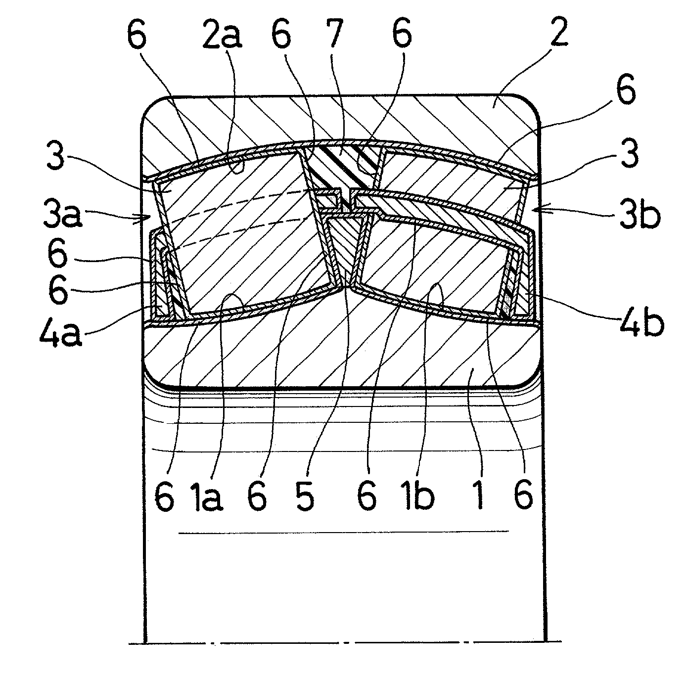
[0033]In a double-row self-aligning roller bearing, as shown in FIG. 3, an outer race having a raceway surface which is arcuate in an axial section can be freely swung about an axis perpendicular to the bearing center axis, with respect to an assembly configured by an inner race, two rolling element rows, and two cages respectively holding the rolling element rows. When annular members which are removable in a state where center axes of the inner and outer races are made incoincident with each other, such as division annular members which are formed by cutting a ring into plural portions are used as the division spacers, therefore, the division spacers can be easily inserted at a position where the space between the inner and outer races is divided in two, i.e., between the rolling element rows in a state where the outer race is shifted so as to make the rotation center axis of the outer race and that of the inner race incoincident with each other as shown in FIG. 3. In the state where the division spacers are inserted, the outer race is returned to its original normal position, or to a state where the rotation center axes of the outer and inner races are made coincident with each other, and the raw materials of the polymeric lubricant are poured between the inner race and the outer race to be solidified. The outer race is again shifted as shown in FIG. 3, so that the division spacers can be removed away. After the removal of the division spacers, the polymeric lubricant between the outer and inner races is in the state where it is axially divided in two at an axial center portion, with the result that a polymeric lubricant packed bearing having independent polymeric lubricants that are disposed respectively for rolling element rows can be obtained.

Problems solved by technology

When one of the above-mentioned conventional lubrication techniques is used in such a self-aligning roller bearing, therefore, there arises the possibility that lubricating oil or the grease leaks out to the outside of the bearing.
When a rolling bearing of the grease packed type is used as a rolling bearing to be placed at, for example, a high overhead location or an inner location of an apparatus, it is difficult to conduct lubrication maintenance such as grease additional injection.
In such a polymeric lubricant packed bearing, the polymeric lubricant is in contact with the rolling elements or the inner and outer races to generate a sliding frictional resistance, thereby producing produces problems in that the rotational torque of the bearing is increased, and that the rolling bearing is self-heated by the sliding frictional resistance and the polymeric lubricant is melted and damaged.
Furthermore, in a roller bearing or the like, particularly, even when an oil film is formed by lubricating oil, the above-mentioned sliding frictional resistance cannot be sufficiently reduced, thereby producing a problem in that required low-torque characteristics cannot be attained.
As a result, particularly in the use at a high speed, the leading or lagging between the rolling element rows causes a large force to act on the polymeric lubricant, thereby causing the possibility that the polymeric lubricant is damaged.
In the state of the art, therefore, a polymeric lubricant packed bearing having such a structure has not yet been practically used.
However, it is very difficult to fit a polymeric lubricant which is previously shaped together with a rolling element row and a cage into a doughnut-like form, between inner and outer races.
However, this method has problems in that a mold which has many small cavities for respectively housing the columnar portions of each cage is additionally required, and also that there is the possibility that the polymeric lubricant is peeled off or damaged by a force which is applied during a process of placing the cage into a bearing and inserting rolling elements into respective pockets.

Method used


Image

  • Polymeric lubricant packed bearing and method of producing the same
  • Polymeric lubricant packed bearing and method of producing the same
  • Polymeric lubricant packed bearing and method of producing the same

Examples


Embodiment Construction

[0043]Hereinafter, embodiments of the invention will be described with reference to the accompanying drawings.

[0044]FIG. 1 is an axial section view showing the configuration of an embodiment in which the invention is applied to a double-row self-aligning roller bearing. In FIG. 1, for the sake of convenience of description, also rolling elements 3 are shown in section.

[0045]Between an inner race 1 in which two raceway surfaces 1a and 1b are formed in the outer periphery, and an outer race 2 in which one raceway surface 2a configured by a spherical face is formed in the inner periphery, two rolling element rows 3a and 3b each configured by a plurality of rolling elements 3 are placed so as to respectively correspond to the raceway surfaces 1a and 1b so as to be rollable with respect to both the raceway surface 1a or 1b and the raceway surface 2a of the outer race 2 in a state where the rolling elements are held at a constant pitch in the circumferential direction by respective cages ...


PUM


Abstract

A film composed of grease, or a film composed of a thickener for grease, is formed on a portion of the surface of each of components constituting a bearing, the portion being opposed to a polymeric lubricant, whereby sliding frictional resistance between the bearing components and the polymeric lubricant is reduced. In the formation of the film, the assembled bearing in which the film has not yet been formed is immersed into a liquid which is obtained by diluting the grease or the thickener for grease with a solvent, and the solvent is then dried, thereby to highly reproducibly form the film of uniform thickness. In an assembled double-row self-aligning roller bearing wherein an outer race is swingable in a direction perpendicular to the center axis of the bearing, raw materials of a polymeric lubricant are poured into and solidified in two regions of an annular space between the inner and outer races.

Description

FIELD OF THE INVENTION[0001]The present invention relates to a polymeric lubricant packed bearing in which a polymeric lubricant is packed in a space formed among an inner race of a rolling bearing, an outer race, and rolling elements, a method of producing such a bearing, and a method of producing a polymeric lubricant packed bearing in which a polymeric lubricant is packed between inner and outer races of a double-row self-aligning roller bearing.BACKGROUND OF THE INVENTION[0002]In a rolling bearing, in order to improve the lubricity between an inner raceway surface and rolling elements, or an outer raceway surface and the rolling elements, usually, lubricating oil is supplied into or grease is packed in an annular space formed between an inner race and an outer race. In order to supply lubricating oil or to pack grease in such a space between the inner race and the outer race, or to prevent water, a foreign material, or the like from entering from the outside into the space, a co...

Claims


Application Information

Patent Timeline
IPC IPC(8): F16C33/66F16C19/38F16C23/08F16C33/30F16C33/36F16C33/48F16C33/54F16C33/56F16C33/64
CPCF16C19/38F16C23/086F16C33/6611F16C33/495F16C33/543F16C33/48F16C33/36
Inventor NAKATA, RYUJIKOMIYA, HIROSHI
Owner KOYO SEIKO CO LTD
Why Eureka
Try Eureka