Method and apparatus for forming thermoplastic resin foam

a thermoplastic resin and foam technology, applied in the field of apparatus and method can solve the problems of complex structure of the apparatus for forming thermoplastic resin foam, unsolved problem of sealing carbon dioxide gas inside the heating cylinder, and comparatively high cost, and achieve the effect of high-quality fine foam

Inactive Publication Date: 2006-03-07
JAPAN STEEL WORKS LTD
View PDF33 Cites 10 Cited by
  • Summary
  • Abstract
  • Description
  • Claims
  • Application Information

AI Technical Summary

Benefits of technology

[0007]The present invention was developed to provide a method for forming a thermoplastic resin foam, by which the aforementioned problems can be solved. More specifically, the object of t

Problems solved by technology

There is an unsolved problem of sealing the carbon dioxide gas inside the heating cylinder, which will arise when the carbon dioxide gas under a supercritical state with a pressure considerably higher than the afo

Method used


Image

  • Method and apparatus for forming thermoplastic resin foam
  • Method and apparatus for forming thermoplastic resin foam
  • Method and apparatus for forming thermoplastic resin foam

Examples


Embodiment Construction

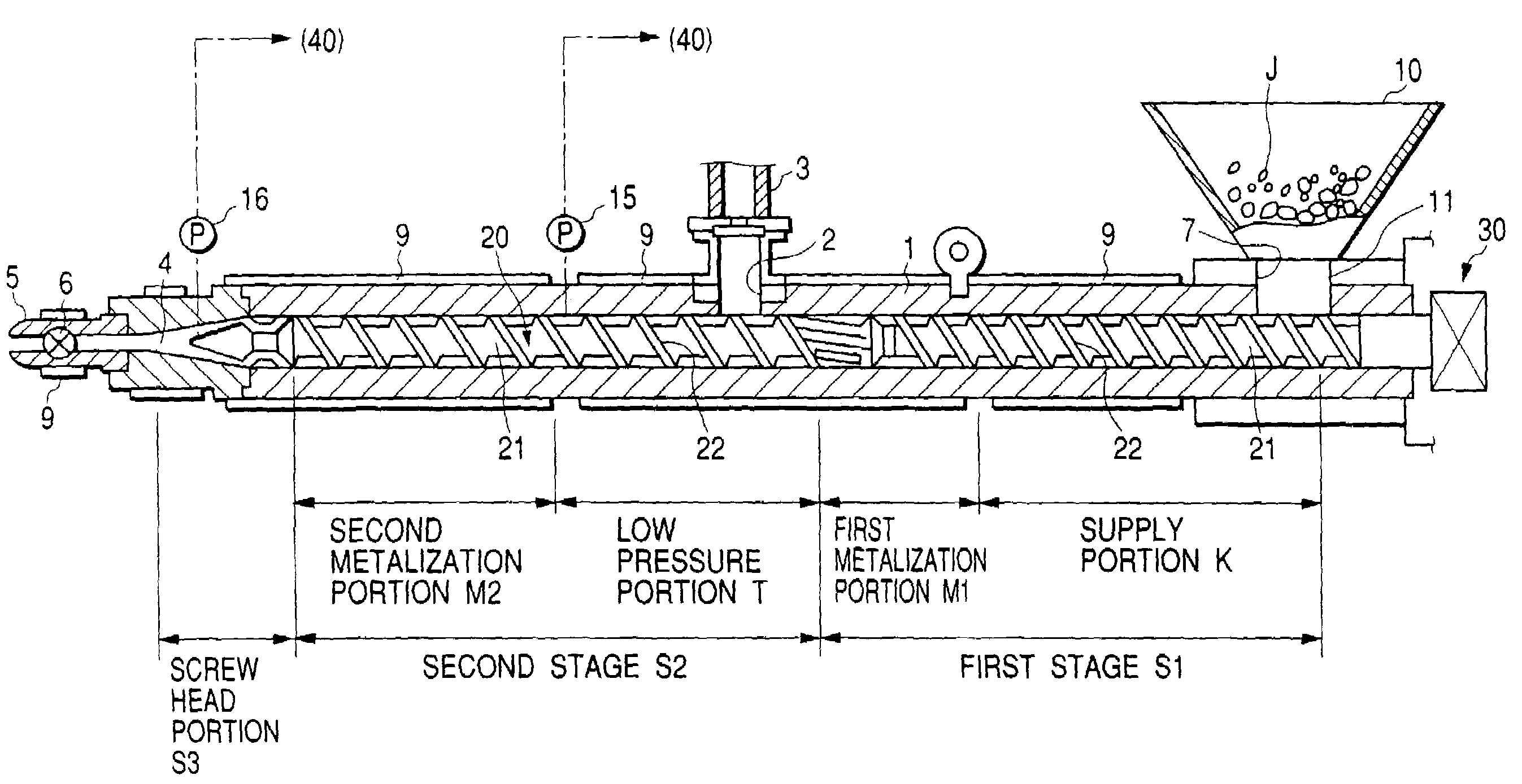
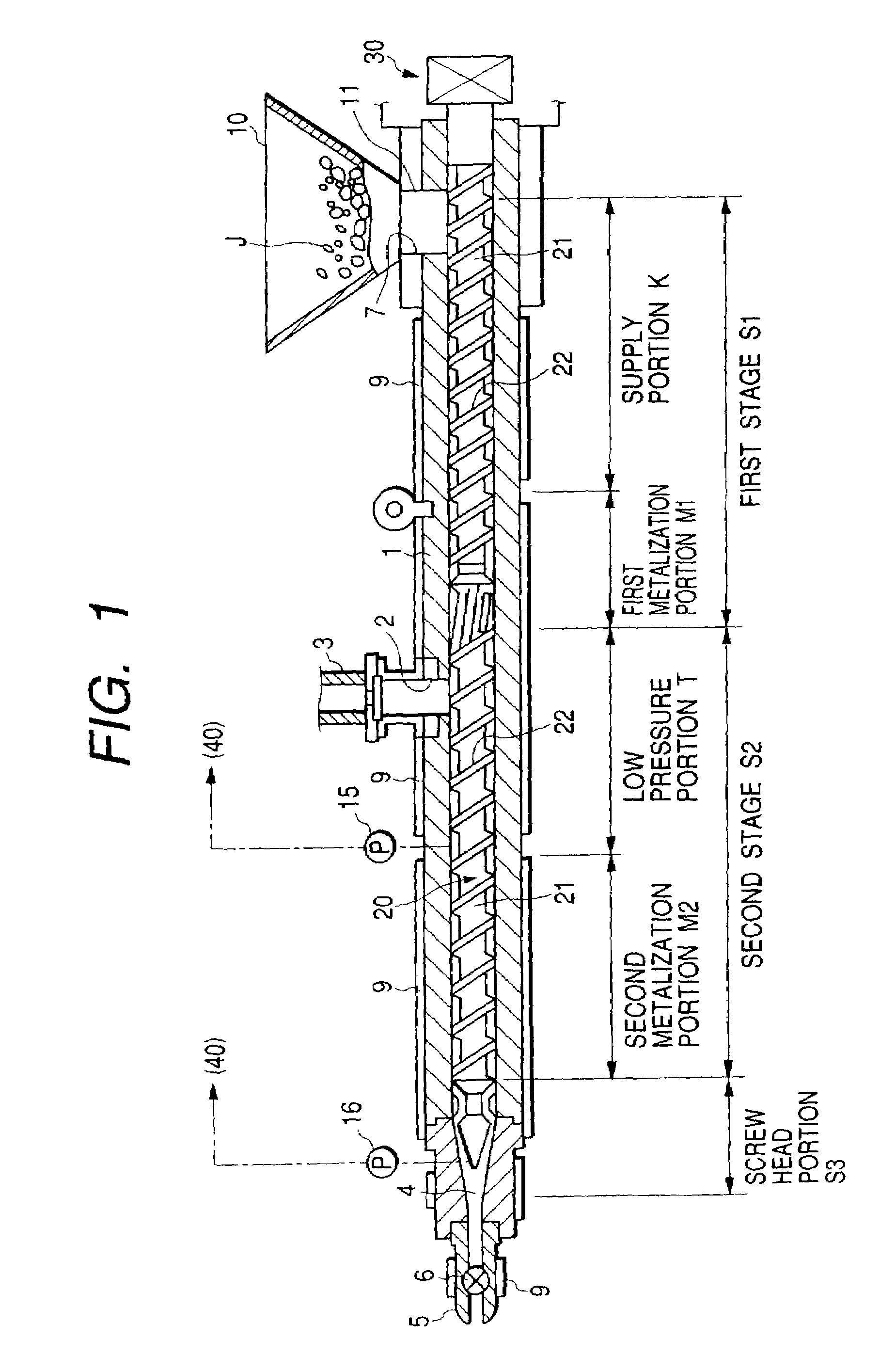
[0018]First, an embodiment of an in-line apparatus for forming a thermoplastic resin foam is explained which is used for carrying out the present invention. FIG. 1 is a cross-sectional schematic front view illustrating part of the embodiment of the apparatus for forming a thermoplastic resin foam. As shown in FIG. 1, the apparatus for forming a thermoplastic resin foam according to the present embodiment comprises generally a screw cylinder 1, a screw 20, and a screw drive unit 30. Here, the screw 20 is rotatably driven into the interior of the screw cylinder 1 in the direction of plasticization, also being rotatably driven in the axial direction or the direction of injection. The screw drive unit 30 is adapted to drive the screw 20 in the direction of plasticization and in the direction of injection.

[0019]The screw cylinder 1 has a predetermined length in the axial direction and is provided with a gas supply hole 2. The gas supply hole 2 is located approximately at the middle porti...


PUM

PropertyMeasurementUnit
Pressureaaaaaaaaaa
Speedaaaaaaaaaa
Thermoplasticityaaaaaaaaaa

Abstract

The present invention relates to the step of plasticizing a thermoplastic resin material by rotatably driving a screw (20). Also included in the method is the step of injecting an inert gas into a screw cylinder (1) to permeate the melted resin and injecting the melted resin into a mold by driving the screw (20) in the direction of injection. Here, the inert gas has a pressure, at least in pressure, equal to or greater than a supercritical pressure or is under a supercritical state. To provide a thermoplastic resin foam by the method, electric servomotors (31, 32) are employed to drive the screw (20). After the step of plasticizing the resin material has been completed, brakes are applied to the electric servomotors (31, 32) to prevent the screw (20) from retreating. Alternatively, even after the step of plasticizing the resin material has been completed, the screw (20) is driven at low speeds in the direction of plasticization until immediately before the step of injecting the melted resin is initiated. This allows foaming inside the screw cylinder (1).

Description

[0001]This is a divisional of application Ser. No. 09 / 800,471 filed Mar. 8, 2001; the disclosure of which is incorporated herein by reference now U.S. Pat. No. 6,726,862.BACKGROUND OF INVENTION[0002]1. Field of Invention[0003]The present invention relates to an apparatus and method for forming a thermoplastic resin foam. The apparatus comprises a screw cylinder and a screw provided drivably in the directions of plasticization and injection inside said screw cylinder. The method comprises the step of injecting an inert gas such as a carbon dioxide gas or a nitrogen gas, having at least in pressure a pressure equal to or greater than a supercritical pressure into said screw cylinder. The method also comprises the steps of permeating melted resin with the inert gas under a supercritical state inside the screw cylinder, and injecting the melted resin, permeated by the inert gas, into a mold to provide a thermoplastic resin foam.[0004]2. Related Art[0005]There have been suggested many ap...

Claims


Application Information

Patent Timeline
IPC IPC(8): B29C44/36B29C44/34B29C48/03B29C48/29B29C48/295
CPCB29C44/3446B29C44/348B29C47/1063B29C47/0009B29C47/1072B29K2105/0005B29C47/1081B29C48/297B29C48/29B29C48/03B29C48/295
Inventor TERAOKA, ATSUOTSUDA, FUMIAKIOHYABU, HIDEO
Owner JAPAN STEEL WORKS LTD
Why Eureka
Try Eureka