Disposable chromatographic columns

a chromatographic column and chromatographic technology, applied in the field of chromatography, can solve the problems of being more susceptible to leakage under pressure than desirable, and the prior art chromatographic column is more expensive than desirable to assemble and can not be used in separation processes, instruments, filtration separation, etc., and achieves the effect of enduring substantial pressur

Inactive Publication Date: 2006-03-07
TELEDYNE INSTR INC
View PDF16 Cites 17 Cited by
  • Summary
  • Abstract
  • Description
  • Claims
  • Application Information

AI Technical Summary

Benefits of technology

[0007]It is a still further object of the invention to provide a novel chromatographic column that can be filled through an open end and then the open end closed with simple linear motion or combined linear engagement followed by rotary motion and then linear disengagement motion.
[0012]In accordance with the above and further objects of the invention, a chromatographic column is formed of a relatively inexpensive material, filled with the desired packing material and then closed at one end, forming a seal that can withstand substantial pressure. In one embodiment, the end is applied with relatively simple substantially linear motion or linear motion to engage the end member and disengage the end member with rotary motion between the engagement and disengagement so as to be capable of being implemented in an automated fashion. A simple linear motion is used with a cap that snaps in place to provide an adequate seal against internal pressures and a linear motion for a machine member to engage the end member for rotating until a spin welded connection is made by friction followed by linear disengaging motion.
[0013]For this purpose, the column is formed of an inexpensive plastic with the tubular body portion and one end with one port being molded as a single piece. A snap-on end piece or an end piece with ridges for grasping with linear motion is also molded as a single piece with a port as an integrally molded part of it and snapped onto or spin welded onto the tubular body portion. The snap on embodiment provides an interference fit adequate to resist leaks at a value above the rated value of the column. Preferably one of the end piece and the open end of the body of the column has snap members that engage detents on the other of the open end of the body and the end piece to hold the two together with adequate force about a tapered connection to form an adequate seal to resist the pressure built up on the column during use. The number of snaps and dimensions are selected to permit the appropriate inexpensive plastic to withstand the stress in use. In the preferred embodiment, the column is made substantially of polypropylene because it is inexpensive and sufficiently inert to withstand usage with normal solvents for a limited number of uses.
[0015]One or both end members have fluid distributing means molded into them for more even flow of fluid through the packing material. In the preferred embodiment, the fluid distributing means are channels in the inlet and outlet end members that open toward the packing material and communicates with the inlet and outlet ports to more evenly distribute fluids.
[0016]From the above description, it can be understood that the method and apparatus of this invention has several advantages, such as: (1) it is economical in terms of its fabricating materials; (2) it is inexpensive to assemble; (3) it can be assembled readily in an automated process; and (4) it can be easily formed of relatively inexpensive materials.

Problems solved by technology

The prior art chromatographic column has the disadvantage of being more costly then desirable to assemble and being more subject to leaks under pressure then desirable.

Method used


Image

  • Disposable chromatographic columns
  • Disposable chromatographic columns
  • Disposable chromatographic columns

Examples


Embodiment Construction

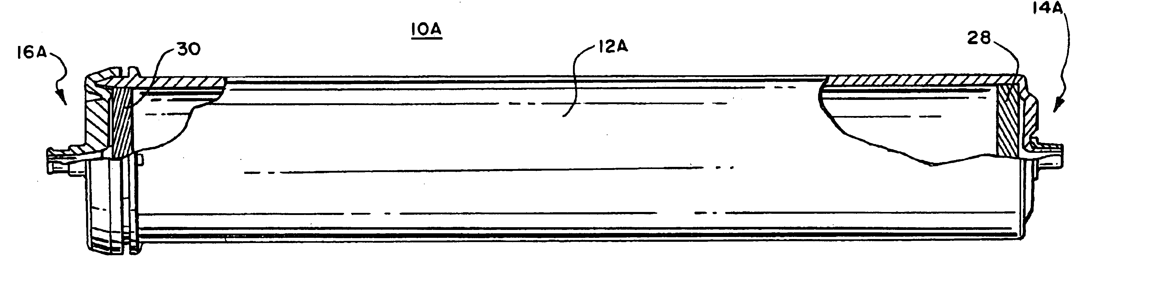
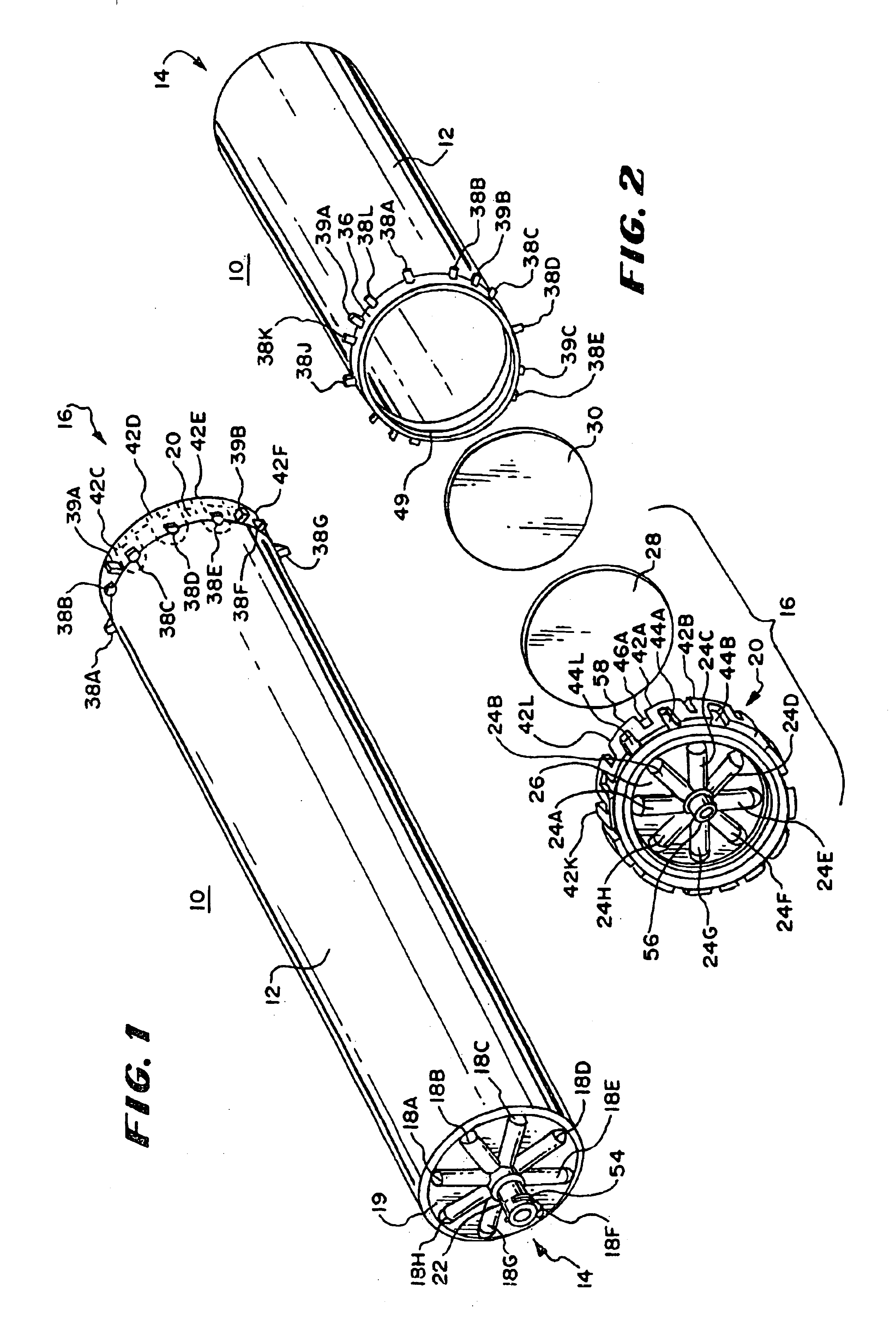
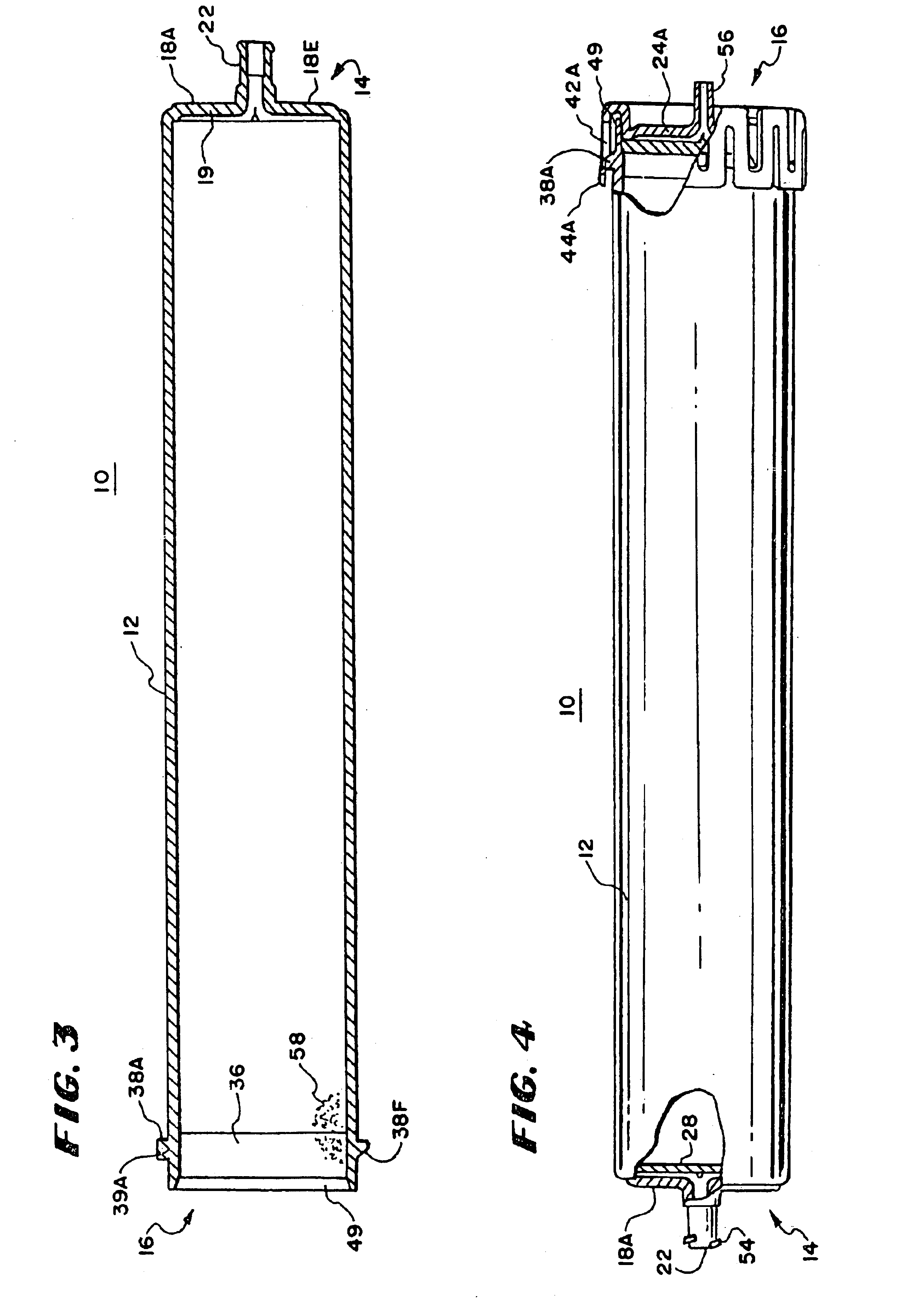
[0030]In FIG. 1, there is shown a column 10 having a column body 12, an inlet end 14 and an outlet end 16 with the direction of flow of fluid being from the inlet end through packing material 58 (FIG. 3) in the tubular column body 12 and out of the outlet end 16 in that order. The inlet end 14 includes a plurality of radially extending inlet channels 18A-18H, a base plate or end portion 19 and an inlet port 22. The column body 12 has a side wall portion integrally molded with a first end and has a second molded open end with outlet and inlet ports molded in end members. At least one of the first and second ends have channels molded in them. The inlet port includes a female luer connection partly threaded at 54 to connect to a source of fluid through a connector which in some embodiments may be spring-biased (not shown in FIG. 1) and extends as a hollow cylindrical tube through the center of the base plate 19 where it communicates with the inlet channels 18A-18H. The inlet port 22 do...


PUM

PropertyMeasurementUnit
thicknessaaaaaaaaaa
operating pressuresaaaaaaaaaa

Abstract

To make an inexpensive chromatographic column and perform chromatography with it, column walls and a column end with a port are molded integrally from plastic. A closure is integrally molded with a port as well. One type of closure includes part of a snap-on fastener integrally molded to it to cooperate with corresponding parts molded integrally with the column walls and another type of closure is welded to the tubular walls. In the preferred embodiment the welding is spin welding. The end and closure have channels molded into them radiating from a port and opening toward packing material such as silica beads or porous polymeric plugs. Filters and secondary seals may be located at the ends to prevent leakage of packing material.

Description

REFERENCE TO RELATED APPLICATIONS[0001]This application is a continuation in part application of U.S. application Ser. No. 10 / 389,626 filed Mar. 14, 2003 entitled DISPOSABLE CHROMATOGRAPHIC COLUMNS, which is a divisional application of U.S. application Ser. No. 09 / 920,124 filed Aug. 1, 2001 entitled DISPOSABLE CHROMATOGRAPHIC COLUMNS, now U.S. Pat. No. 6,565,745.BACKGROUND OF THE INVENTION[0002]This invention relates to chromatography and more specifically to chromatographic columns, methods of making chromatographic columns and methods of using chromatographic columns.[0003]The use of chromatographic columns for the analysis and separation of substances from mixtures has long been known. One type of such column is a disposable column intended for limited use and accordingly manufactured with economy in mind.[0004]One prior art disposable column has been available in commerce for a substantial period of time. It is manufactured of inexpensive plastics and designed to be easily assem...

Claims


Application Information

Patent Timeline
Patent Type & Authority Patents(United States)
IPC IPC(8): B01D15/08B01D15/22G01N30/60
CPCB01D15/22G01N30/6052Y10T29/49604G01N30/6004
Inventor HODGIN, DELWIN D.DAVISON, DALE A.
Owner TELEDYNE INSTR INC
Why Eureka
Try Eureka