Autonomous power source

a power source and autonomous technology, applied in the direction of electric generator control, machines/engines, transportation and packaging, etc., can solve the problems of affecting the performance of the charging system, and the distance required between the tire and the charger may pose a safety concern, so as to reduce the friction experienced by the magnet and high sensitivity to motion

Inactive Publication Date: 2006-03-07
TELEDYNE SCI & IMAGING
View PDF56 Cites 81 Cited by
  • Summary
  • Abstract
  • Description
  • Claims
  • Application Information

AI Technical Summary

Benefits of technology

[0010]The power harvester preferably comprises a closed nonmagnetic tube, with the magnet and bearing enclosed within the tube such that the magnet is free to move within the tube. The coil is preferably wrapped around the exterior of the tube. Motion of the structure to which the harvester is mounted causes the magnet to move with respect to the coil, thereby producing an electrical current in the coil. The use of a ferrofluidic bearing gives the power source a very high sensitivity to motion: the bearing reduces the friction experienced by the magnet to a very low level, such that even a small amount of random motion by the structure is converted to electrical power.

Problems solved by technology

This periodic battery replacement is costly.
The close distance required between tire and charger may pose a safety concern.
In addition, substances such as mud or snow can accumulate on the tire or inductive power source and impede the performance of the charging system.
Unfortunately, this approach makes the external unit an easy target for theft.

Method used


Image

  • Autonomous power source
  • Autonomous power source
  • Autonomous power source

Examples


Embodiment Construction

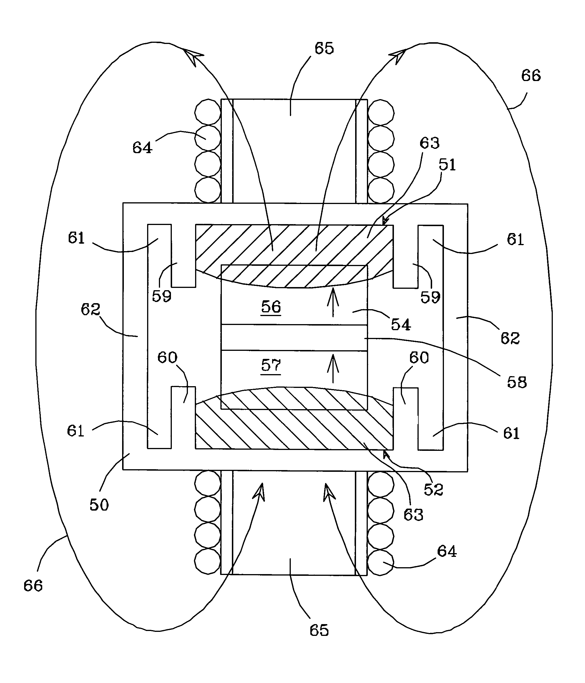
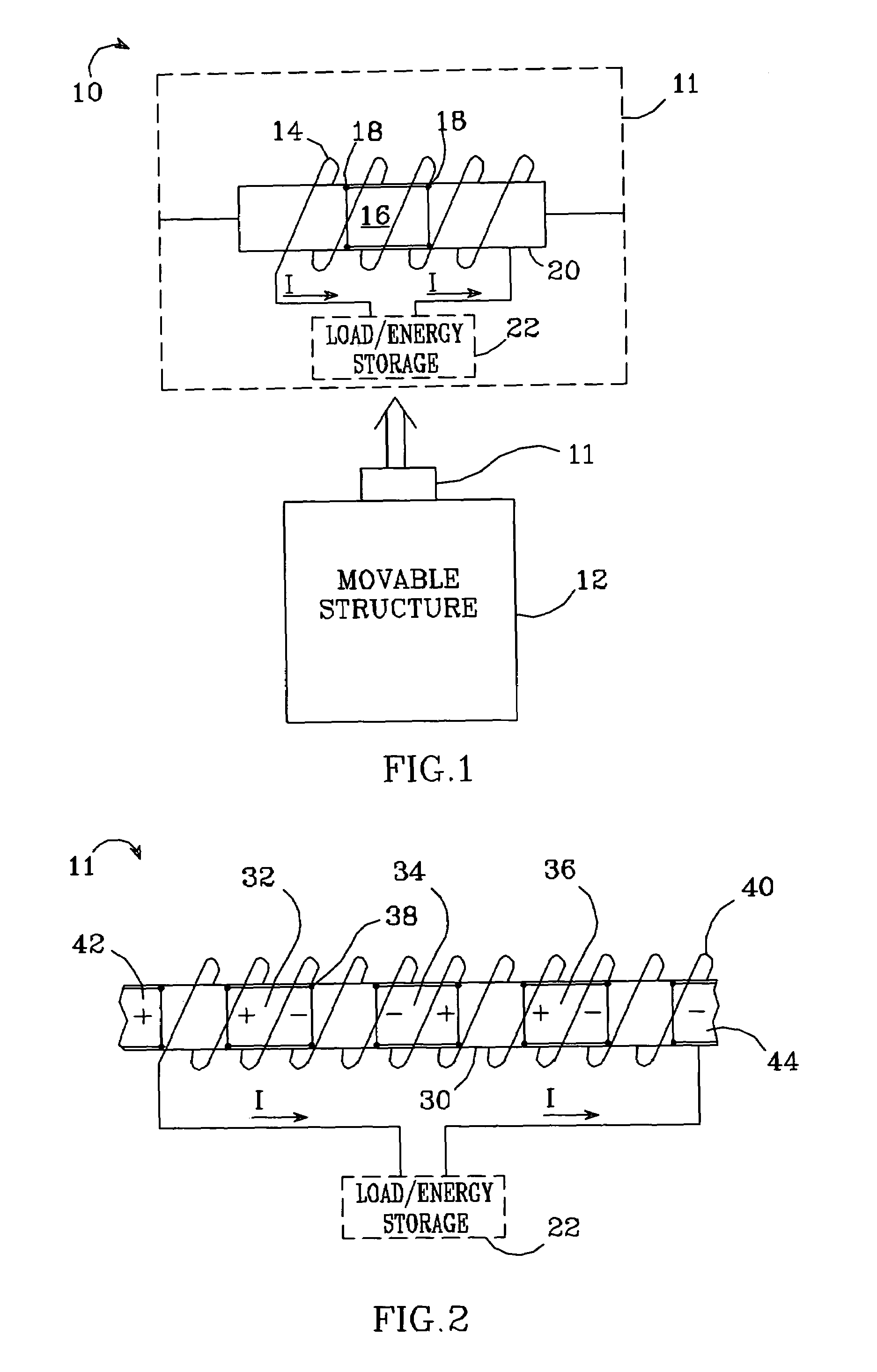
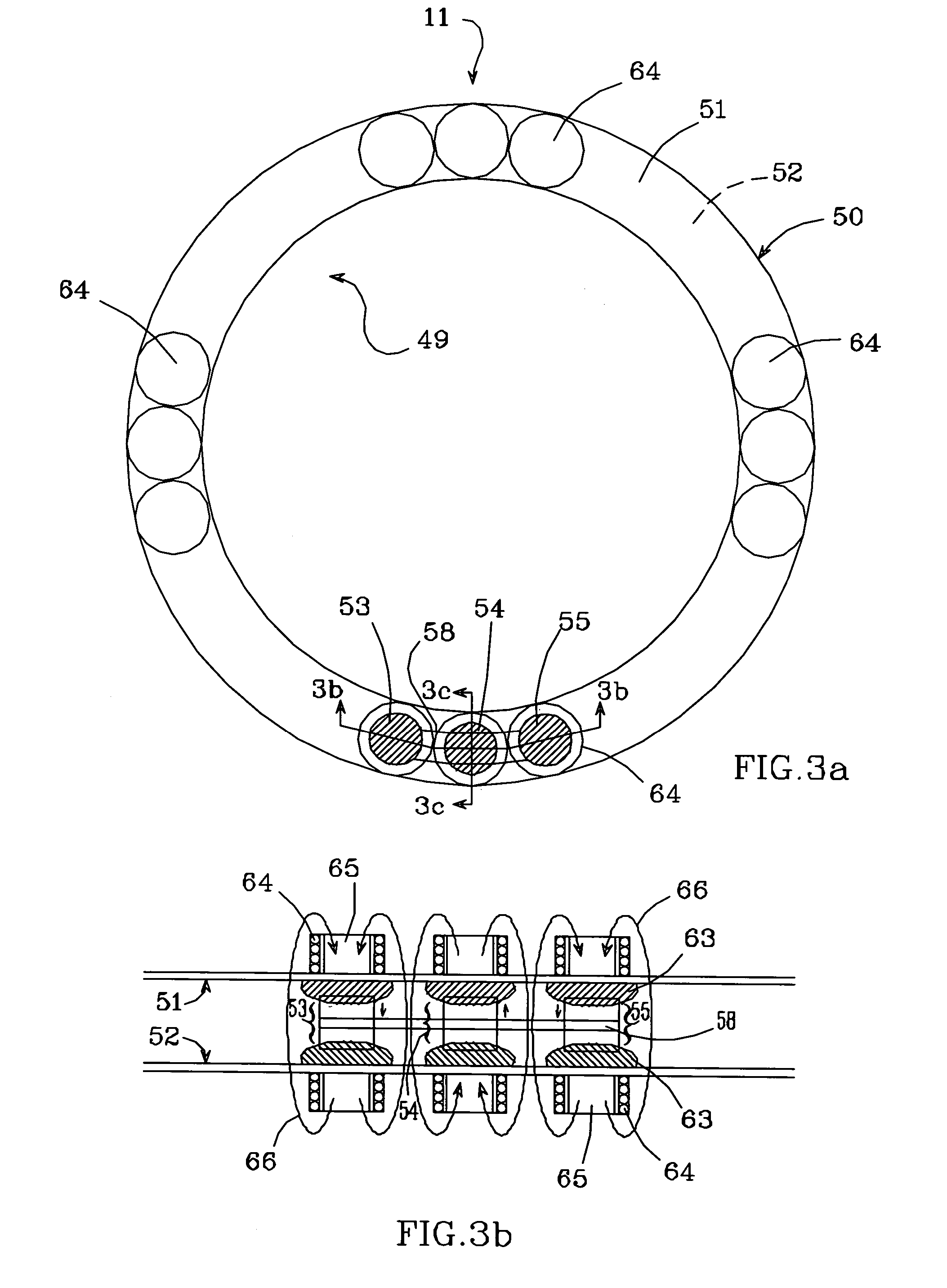
[0028]The present invention is an autonomous power source which converts motion into stored energy; as such, it is particularly well-suited for use as a self-contained power source on a moving vehicle. The basic principles of the invention are illustrated in FIG. 1. An autonomous power source 10 comprises a power harvester 11 mounted onto a movable structure 12 such that it moves with the structure. The power harvester includes at least one conductive coil 14 (typically copper), at least one magnet 16, and a low-friction ferrofluidic bearing 18 in contact with the magnet. In the embodiment shown in FIG. 1, magnet 16 and bearing 18 are enclosed within a nonmagnetic closed tube 20, and coil 14 wraps around the exterior of the tube such that magnet 16 moves with respect to coil 14 as it moves within tube 20. A ferrofluid introduced into tube 20 is naturally attracted to the poles of magnet 16 to form beads 18 around the end poles of the magnet. This provides an ultra low friction lubri...


PUM


Abstract

An autonomous power source comprises a power harvester mounted on a movable structure. The power harvester includes a coil, a magnet, and a low-friction ferrofluidic bearing in contact with the magnet, arranged such that the magnet and coil move with respect to each other when the structure is in motion such that an electrical current is produced in the coil. This current is converted to power and stored in an energy storage system and is thus available to power electronic circuitry. The magnet and bearing are preferably enclosed within a closed linear or circular tube, with the coil mounted around the exterior of the tube. The power harvester and battery are combined with one or more sensors and a wireless transmitter to form a tire pressure monitoring system.

Description

BACKGROUND OF THE INVENTION[0001]1. Field of the Invention[0002]This invention relates to the field of power sources, and particularly to power sources which convert motion into energy.[0003]2. Description of the Related Art[0004]Recently passed government legislation mandates that certain types of vehicles provide on-board, real time tire pressure monitoring—i.e., a system which monitors the air pressure in all vehicle tires. This requires an electronics package to be mounted on or inside the tire or wheel, which is small enough so as to not cause any major weight imbalance. The package would include an air pressure sensor and a means of wirelessly transmitting sensor output data to the vehicle driver, or of storing the data for later retrieval.[0005]The electronics package must be powered, typically by a battery. Several approaches have been considered for the power source. In one approach, a conventional battery is mounted inside the tire, secured to the wheel with a metal band. ...

Claims


Application Information

Patent Timeline
Patent Type & Authority Patents(United States)
IPC IPC(8): H02K33/00F03B13/12H02K35/00H02K7/06H02P9/04F16C33/10H02K7/18
CPCB60C23/041H02K35/00H02K7/1846F16C33/1035
Inventor CHEUNG, JEFFREY T.LATTY, JAMES A.
Owner TELEDYNE SCI & IMAGING
Why Eureka
Try Eureka